Application Note
31 of 38
001-86233 Rev. *I
2021-11-04
PSoC™ 4 MCU low
-power modes and power reduction techniques
PSoC™ Creator hardware configuration
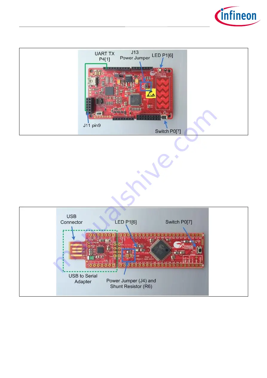
Figure 16
CY8CKIT-042 kit hardware
CY8CKIT-044 and CY8CKIT-046 are similar to CY8CKIT-042 and have similar connections for the switch, LED, and
UART Tx lines. See the kit guides provided on the respective web pages for more information on these kits.
9.2
CY8CKIT-049-42xx kit (PSoC™ 4200)
These low-cost kits provide access to all
PSoC™
4 MCU pins, and include a user LED and switch that are
compatible with CY8CKIT-
042. Power can be provided from one of the “P4VDD” pins on the side or through the
USB connector at the end.
shows the kit hardware.
Figure 17
This kit does not have a built-in debugger, but it includes a USB-to-serial adapter that can be used to bootload
the project. The projects must first be modified to include a bootloadable component to use this interface. If
you have a MiniProg3 program and debug kit (CY8CKIT-002), you can connect it directly to a user-installed
connector at the bottom-right corner of the board. For more information on how to use the USB-to-serial
adapter for bootloading, download the kit documentation from the website.


