Chapter 1:
Introduction
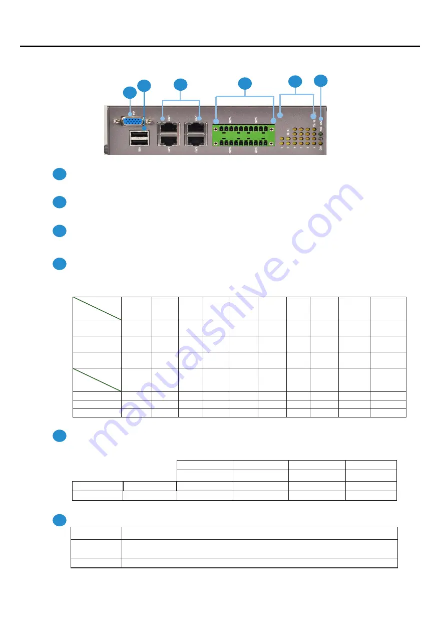
VGA Port
Port for the connection of a monitor using a suitable DB-15 cable
Two USB 2
0 type A ports
Connects to any USB device, for example, a flash drive
Four 10/100/1000Mbps LAN ports
Using suitable RJ-45 cable, you can connect IMM-L30D System to a computer, or to any other piece of equipment
that has an Ethernet connection such as a hub or a switch
20-pin Phoenix Contact Terminal Block
This connector can be connected for 4 Com ports (COM4: Pin 1~5, Com3: Pin 6~10, Com2: Pin11~15, Com1: Pin
16~20) with serial port type of RS-232, RS-422 or RS-485; it supports dip switch selection of RS-232, RS-422 and
485 The following table lists the pin assignments
Pin NO.
Port Type
Pin 1
Pin 2
Pin 3
Pin 4
Pin 5
Pin 6
PIN7
PIN 8
PIN 9
Pin10
RS-232
Ground
(GND)
CTS4# SOUT4 SIN4
RTS4#
GND
CTS3# SOUT3 SIN3
RTS3#
RS-422
Ground
(GND)
RX-
RX+
TX+
TX-
GND
RX-
RX+
TX+
TX-
RS-485
Ground
(GND)
NC
NC
DATA+ DATA- GND
NC
NC
DATA+ DATA-
Pin NO.
Port Type
Pin 11
Pin 12 Pin 13 Pin 14
Pin 15
Pin 16 Pin 17 Pin 18
Pin 19
Pin 20
RS-232
GND
CTS2# SOUT2 SIN2
RTS2#
GND
CTS1# SOUT1 SIN1
RTS1#
RS-422
GND
RX-
RX+
TX+
TX-
GND
RX-
RX+
TX+
TX-
RS-485
GND
NC
NC
DATA+ DATA- GND
NC
NC
DATA+ DATA-
Serial Port Status LED
The upper two rows are LED indicators for the Digital Inputs and Outputs
The bottom two roles are LED indicators of Tx (Data transmitting) and RX (Data receiving) for serial port Status
Power/Status/HDD LED
Power
Green indicates Power-on, where as Off indicates Power-off status.
Run
A programmable dual green/orange LEDs which can be used for indicating
system status.
Hard Disk
Yellow indicates that HDD is present, whereas Off indicates HDD is not present.
Front Panel Features
F1
F4
F3
F2
F5
F6
1 1 1 2 1 3 1 4 1 5 1 6 1 7 1 8 1 9 2 0
1 2 3 4 5 6 7 8 9 1 0
LAN1 LAN3
LAN2 LAN4
DO-Pin 4
DO-Pin 3
DO-Pin 2
DO-Pin 1
DI-Pin 4
DI-Pin 3
DI-Pin 2
DI-Pin 1
TX-COM 6
TX-COM 5
TX-COM 4
TX-COM 3
TX-COM 2
TX-COM 1
RX-COM 6
RX-COM 5
RX-COM 4
RX-COM3
RX-COM 2
RX-COM 1
F1
F2
F3
F4
F5
F6
IM
M
-
L30D
User Manual
2


