background image

GB

9

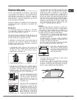
Connection with a rigid pipe (copper or steel)

!

 Connection to the gas system must be carried out in such a 

way as not to place any strain of any kind on the appliance.

There is an adjustable L-shaped pipe fitting on the appliance 

supply ramp and this is fitted with a seal in order to prevent 

leaks. The seal must always be replaced after rotating the 

pipe fitting (seal provided with appliance). The gas supply 

pipe fitting is a threaded 1/2 gas cylindrical male attachment.

Connecting a flexible jointless stainless steel pipe to 

a threaded attachment

The gas supply pipe fitting is a threaded 1/2 gas cylindrical 

male attachment.

These pipes must be installed so that they are never longer 

than 2000 mm when fully extended. Once connection has 

been carried out, make sure that the flexible metal pipe 

does not touch any moving parts and is not compressed.

!

 Only use pipes and seals that comply with current national 

regulations.

Checking the tightness of the connection

!

 When the installation process is complete, check the pipe 

fittings for leaks using a soapy solution. Never use a flame.

Adapting to different types of gas

To adapt the hob to a different type of gas other than default 

type (indicated on the rating plate at the base of the hob or 

on the packaging), the burner nozzles should be replaced 

as follows:

1. Remove the hob grids and slide the burners off their 

seats.

2. Unscrew the nozzles using a 7 mm socket spanner, and 

replace them with nozzles for the new type of gas (see 

table 1 “Burner and nozzle characteristics”).

3. Reassemble the parts following the above procedure in 

the reverse order.

4. Once this procedure is finished, replace the old rating 

sticker with one indicating the new type of gas used. 

Sticker are available from any of our Service Centres.

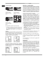
Replacing the Triple ring burner nozzles

1. Remove the pan supports and lift the burners out of their 

housing. The burner consists of two separate parts (see 

pictures).

2. Unscrew the nozzles using a 7 mm socket spanner. 

Replace  the  nozzles  with  models  that  are  configured 

for use with the new type of gas (see Table 1). The two 

nozzles have the same hole diameter.

3. Replace all the components by completing the above 

operations in reverse order.

•  Adjusting the burners’ primary air

Does not require adjusting.

•  Setting the burners to minimum

1. Turn the tap to the low flame position;

2. Remove the knob and adjust 

the adjustment screw, which is 

positioned in or next to the tap pin, 

until the flame is small but steady.

3. Having adjusted the flame to the required low setting, 

while the burner is alight, quickly change the position 

of the knob from minimum to maximum and vice versa 

several times, checking that the flame does not go out.

4. Some appliances have a safety device (thermocouple) 

fitted. If the device fails to work when the burners are set 

to the low flame setting, increase this low flame setting 

using the adjusting screw.

5. Once the adjustment has been made, replace the 

seals on the by-passes using sealing wax or a similar 

substance.

!

 If the appliance is connected to liquid gas, the regulation 

screw must be fastened as tightly as possible.

!

  Once  this  procedure  is  finished,  replace  the  old  rating 

sticker with one indicating the new type of gas used. Stickers 

are available from any of our Service Centres.

!

 Should the gas pressure used be different (or vary slightly) 

from the recommended pressure, a suitable pressure 

regulator must be fitted to the inlet pipe (in order to comply 

with current national regulations).

Electrical 

connections

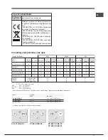
DATA PLATE

see data plate

This appliance conforms to the following 

European Economic Community directives:

- 2006/95/EEC dated 12/12/06 (Low 

Voltage) and subsequent amendments

- 2004/108/EEC dated 15/12/04 

(Electromagnetic Compatibility) and 

subsequent amendments

- 93/68/EEC dated 22/07/93 and 

subsequent amendments.

- 2009/142/EEC dated 30/11/09 (Gas) and 

subsequent amendments.

- 2012/19/EC and subsequent 

amendments.

Summary of Contents for PC 631 HA PL

Page 1: ...is treści Instrukcja obsługi 1 Ostrzezenia 2 Serwis Techniczny 4 Opis urządzenia 5 Instalacja 14 Uruchomienie i użytkowanie 18 Zalecenia i środki ostrożności 18 Konserwacja i utrzymanie 19 Anomalie i środki zaradcze 20 Polski Instrukcja obsługi PŁYTA Magyar Használati útmutató FŐZŐLAP Tartalomjegyzék Használati útmutató 1 Figyelmeztetések 3 Szerviz 4 A készülék leírása 6 Üzembe helyezés 21 Bekapcs...

Page 2: ...intended to be operated by means of an external timer or separate remote control system CAUTION the use of inappropriate hob guards can cause accidents Ostrzezenia UWAGA To urządzenie oraz jego dostępne części silnie się rozgrzewają podczas użytkowania Należy uważać aby nie dotknąć elementów grzejnych Nie pozwalać aby dzieci poniżej 8 roku życia zbliżały się do urządzenia jeśli nie są pod stałym n...

Page 3: ...merő személyek csak megfelelő felügyelet mellett vagy a készülék biztonságos használatával kapcsolatos alapvető utasítások és a kapcsolódó veszélyek ismeretében használhatják Vigyázzon hogy a gyermekek ne játsszanak a készülékkel A tisztítási és karbantartási műveleteket gyermekek felügyelet nélkül nem végezhetik FIGYELEM Atűzhelyen felügyelet nélkül otthagyott zsír vagy olaj veszélyes lehet és tü...

Page 4: ...nal Serwis Techniczny Nigdy nie korzystać z usług nieautoryzowanych techników Podać Rodzaj usterki Model urządzenia Mod Numer seryjny S N Te ostatnie informacje można znaleźć na tabliczce znamionowej umieszczonej na urządzeniu Szerviz Sohase hívjon engedéllyel nem rendelkező szakembert Adja meg az alábbiakat az anomália típusa a készülék modellje Mod a készülék szériaszáma S N Az utóbbi információ...

Page 5: ...anego palnika URZĄDZENIE ZABEZPIECZAJĄCE w razie przypadkowego zgaśnięcia płomienia przerywa dopływ gazu Tylko w niektórych modelach Description of the appliance Overall view 1 Support Grid for COOKWARE 2 GAS BURNERS 3 ELECTRIC HOTPLATE 4 Electric HOTPLATE INDICATOR LIGHT 5 Control Knobs for GAS BURNERS 6 Control Knobs for ELECTRIC HOTPLATES 7 Ignition for GAS BURNERS 8 SAFETY DEVICES ELECTRIC HOT...

Page 6: ...EKTROMOS FŐZŐMEZŐK különböző méretűek és különböző teljesítményűek lehetnek A teljesítmény szint lehet normál vagy gyors az utóbbi a főzőmező közepénél levő piros foltról ismerhető fel GÁZÉGŐK Különböző méretűek és teljesítményűek Válassza a használni kívánt edény átmérőjének leginkább megfelelőt AGÁZ ÉGŐ és ELEKTROMOS FŐZŐMEZŐ üzemeltető gombok szabályozzák a teljesítményt és a láng nagyságát GYÚ...

Page 7: ...tion tubes as described above However these rooms must not be communal rooms bedrooms or rooms that may present a fire hazard A Examples of ventilation holes for comburant air Enlarging the ventilation slot between window and floor Adjacent Room Room to be Vented Liquid petroleum gas sinks to the floor as it is heavier than air Therefore rooms containing LPG cylinders must also be equipped with ve...

Page 8: ...or the charge indicated and must comply with current electrical regulations the earthing wire must not be interrupted by the circuit breaker The supply cable must not come into contact with surfaces with temperatures higher than 50 C The installer must ensure that the correct electrical connection has been made and that it is compliant with safety regulations Before connecting to the power supply ...

Page 9: ...rners out of their housing The burner consists of two separate parts see pictures 2 Unscrew the nozzles using a 7 mm socket spanner Replace the nozzles with models that are configured for use with the new type of gas see Table 1 The two nozzles have the same hole diameter 3 Replace all the components by completing the above operations in reverse order Adjusting the burners primary air Does not req...

Page 10: ...y A Triple Crown TC 100 100 75 55 130 0 75 0 75 0 45 0 45 1 60 3 40 2 75 1 80 1 05 3 50 39 39 28 28 61 91 80 64 50 65x2 247 200 131 76 254 243 196 129 75 250 3 50 3 00 1 90 1 10 3 80 132 H 122 H 96 79 6 103x2 333 286 181 105 362 3 40 2 50 1 64 1 00 3 20 131 Y 122 H 96 79 6 103x2 376 277 181 111 354 Burner and nozzle specifications At 15 C and 1013 mbar dry gas G31 P C S 50 37 MJ Kg G30 P C S 49 47...

Page 11: ...ates The corresponding knob may be turned clockwise or anti clockwise and set to six different positions Setting Normal o Fast Plate 0 Off 1 Low 2 5 Medium 6 High When the selector knob is in any position other than the off position the on light comes on Practical advice on using the burners To ensure the burners operate efficiently Use appropriate cookware for each burner see table so that the fl...

Page 12: ... reduced physical sensory or mental capacities by inexperienced individuals or by anyone who is not familiar with the product These individuals should at the very least be supervised by someone who assumes responsibility for their safety or receive preliminary instructions relating to the operation of the appliance Do not let children play with the appliance The appliance is not intended to be ope...

Page 13: ...rectly There are draughts near the appliance The flame dies in models with a safety device Check to make sure that You pressed the knob all the way in You keep the knob pressed in long enough to activate the safety device The gas holes are not blocked in the area corresponding to the safety device The burner does not remain lit when set to minimum Check to make sure that The gas holes are not bloc...

Page 14: ...zczeniami sypialni lub w których występuje zagrożenie pożarem A Skroplone gazy pochodne ropy naftowej cięższe od powietrza opadają w dół Dlatego pomieszczenia w których przechowywane są butle GPL powinny przewidywać otwory prowadzące na zewnątrz umożliwiające spływanie ku dołowi ewentualnych wycieków gazu Ponadto butle GPL niezaleznże od tego czy są puste czy częściowo napełnione nie powinny być i...

Page 15: ...onowej Wprzypadkubezpośredniegopodłączeniadosiecikoniecznym jestzainstalowaniepomiędzyurządzeniemasieciąwyłącznika polowego z otwarciem minimalnym pomiędzy stykami 3 mm przeznaczonego do obciążeń i odpowiadającego obowiązującym normom przewód uziemienia nie powinien być przerywany przez wyłącznik Przewód zasilania powinien być umieszczony w taki sposób aby w żadnym punkcie temperatura otoczenia ni...

Page 16: ... rurowym 7mm i wymienić je na nowy rodzaj przystosowany do nowego rodzaju gazu patrz tabela 1 Charakterystyki palników i dysz 3 ponownie zmontować części w kolejności odwrotnej 4 na zakończenie czynności wymienić poprzednią etykietę regulacyjna na nową odpowiadająca nowemu paliwu dostepną w naszych centrach obsługi technicznej Wymiana dysz palnika Potrójna Korona 1 Zdjąć ruszt z płyty i wyjąć paln...

Page 17: ...cieplna p c s kW Min Moc cieplna p c s kW Mak Moc cieplna p c s kW Mak Moc cieplna p c s kW Mak 0 75 0 75 0 40 0 40 1 60 Średnica 1 100 mm minimalne mbar nominalne mbar maksymalne mbar 100 100 75 55 130 Dysza 1 100 w mm 122 H3 132 H3 96 Y 79 6 103 x2 2 70 3 00 1 65 1 00 3 60 Przepływ l godz 285 257 157 95 343 2 70 3 00 1 65 1 00 3 30 2 90 3 30 1 80 1 05 3 60 Dysza 1 100 w mm 171 183 130 106 138 x2...

Page 18: ...tać co następuje stosować naczynia odpowiednie dla każdego z palników patrz tabela w celu uniknięcia wychodzenia płomieni poza pole dna naczyń Tylko w niektórych modelach stosować zawsze naczynia o dnie płaskim i z przykrywką w chwili zagotowania się obrócić pokrętło do położenia minimum Palnik Szybki zmniejszony RR Szybki R Półszybki średni S Pomocniczy mały A Potrójna korona TC Ø Średnica naczyń...

Page 19: ...co do jego użytku Urządzenie nie jest przeznaczone do tego aby było włączane przy użyciu zewnętrznego przekaźnika czasowegolubosobnegosystemusterowaniazdalnego Usuwanie odpadów Usuwanie materiałów opakowaniowych dostosować się do lokalnych przepisów w ten sposób opakowanie będzie mogło zostać odzyskane Europejska Dyrektywa 2012 19 EC dotycząca Zużytych Elektrycznych i Elektronicznych Urządzeń WEEE...

Page 20: ...nika Występują przeciągi w sąsiedztwie płyty kuchennej Płomień nie zostaje zapalony w wersjach z zabezpieczeniem Sprawdzić i upewnić się Nie wdusiliście do końca pokrętła Nie przytrzymaliście wduszonego do końca pokrętła przez czas wystarczający do uruchomienia urządzenia zabezpieczającego Są pozatykane otwory wylotowe gazu w pobliżu urządzenia zabezpieczającego Palnik w położeniu minimum nie pali...

Page 21: ...k szerint a szabadba nyitott szellőzőnyílással kell rendelkezniük kivéve közös légterű helyiségek tűzveszélyes helyiségek vagy hálószoba esetén A Példák az égési levegő szellőzőnyílására Az ajtó és padló közti rés növelése Szomszédos helyiség Szellőztetendő helyiség A levegőnél nehezebb cseppfolyósított gázok megülnek a padlószinten Ezért a cseppfolyósítottgáz tartályok tárolására szolgáló helyisé...

Page 22: ...vényben lévő szabványoknak megfelelő legalább 3 mm es omnipoláris kapcsolót kell beszerelni a földkábelt nem szabad megszakítóval ellátni A hálózati kábelt úgy kell elhelyezni hogy sehol se melegedhessen a szobahőmérsékletnél 50 C kal magasabb hőmérsékletre A készülék beszerelője felelős a megfelelő elektromos csatlakoztatásért és a biztonsági előírások betartásáért A csatlakoztatás előtt győződjö...

Page 23: ...űvelet végeztével cserélje le a régi gázkalibrálási címkét az új használati gáztípusnak megfelelőre mely valamennyi hivatalos szakszervizünkben beszerezhető A gázégők primer levegőjének beszabályozása A gázégők nem igénylik a primer levegő beszabályozását Minimális beszabályozás 1 Csavarja a gázégő szabályozó csapját minimumra 2 Húzza le a tekerőgombot és csavarja a tekerőgomb tengelyében vagy ame...

Page 24: ...5 0 45 1 60 3 40 2 75 1 80 1 05 3 50 39 39 28 28 61 91 80 64 50 65x2 247 200 131 76 254 243 196 129 75 250 3 50 3 00 1 90 1 10 3 80 132 H 122 H 96 79 6 103x2 333 286 181 105 362 3 40 2 50 1 64 1 00 3 20 131 Y 122 H 96 79 6 103x2 376 277 181 111 354 Gázégő és gázfúvóka jellemző adatai 15 C on és 1013 25 mbar gáz G31 P C S 50 37 MJ Kg G30 P C S 49 47 MJ Kg G20 P C S 37 78 MJ m G25 1 P C S 32 51 MJ m...

Page 25: ...tja a be ellenőrző lámpa bekapcsol Praktikustanácsokagázégőkhasználatához A maximális teljesítmény elérése érdekében ajánlatos betartani a következőket Használjon a gázégőhöz illő edényeket lásd táblázat hogy a lángok ne érjenek túl az edények alján Mindig csak lapos fenekű és fedővel rendelkező edényeket használjon A forrás pillanatában forgassa a tekerőgombot a legkisebb fokozatra Égő Gyors égő ...

Page 26: ...nálló távvezérléssel legyen működtetve Hulladékkezelés A csomagolóanyag hulladékkezelése tartsa be a helyi előírásokat így a csomagolóanyag újra felhasználásra kerülhet Az Európai Parlament és Tanács elektromos és elektronikus berendezések hulladékairól WEEE szóló 2012 19 EK irányelve előírja hogy e hulladékok nem kezelhetők háztartási hulladékként A forgalomból kivont berendezéseket az azokat alk...

Page 27: ...tekerőgombot Nem nyomta be tövig a tekerőgombot elég ideig ahhoz hogy bekapcsoljon a biztonsági szerkezet Abiztonsági szerkezethez tartozó gázkimenet eltömődött A gázégő a legkisebb fokozatban kialszik Ellenőrizte hogy A gázkimenetek eltömődtek A főzőlap közelében huzat van A legkisebb fokozat nincs megfelelően beszabályozva Az edények instabilak Ellenőrizte hogy Az edény feneke teljesen lapos Az ...

Page 28: ...28 HU 195109147 00 11 2012 XEROX FABRIANO ...

Reviews: