


6
EN
INSTALLATION TIPS
Positioning
Important: this unit may be installed and used only in
permanently ventilated rooms according to the
British Standards Codes Of Practice: B.S. 6172/B.S. 5440, Par.
2 and B.S. 6891 Current Editions. The following
requirements must be observed:
a)
The cooker should not be installed in a bed sitting
room with a volume of less than 20m
3
. If it is installed in a
room of volume less than 5m
3
an air vent of effective area
of 110cm
2
is required, if it is installed in a room of volume
between 5m
3
and 10m
3
a supplementary airvent area of
50cm2 is required, if the volume exceeds 11m
3
no airvent is
required. However, if the room has a door or a window which
opens directly to the outside no air vent is required even
when the volume is between 5m
3
and 11m
3
.
b)
During prolonged use of the appliance you may
consider it necessary to open a window to the outside to
improve ventilation.
c)
If there are other fuel burning appliances in the
same room, B.S.5440 Part 2 Current Edition, should, be
consulted to determine the requisite air vent requirements.
This appliance must be earthed.
Mains Connection
Your cooker should have been checked to ensure that
the voltage corresponds with your supply voltage,
this is stated on the rating plate, which is situated on
the outer rear panel.
The model number and serial number are located on the
front of the cooker, as shown on the Feature's page.
The cooker must be connected by a competent person
such as one who is a, NICEIC registered contractor to a
suitable double-pole control unit with a minimum rating
of 32A and a minimum contact clearance of 3mm
(applicable to newer properties, older properties where a
30A double pole control unit and a minimum contact
clearance of 3mm is acceptable).
The double pole control unit should be fitted
adjacent to the cooker, in accordance with IEE regulations.
The control unit must be within 2 meters of but not
directly above the appliance and should be easily
accessible in the event of an emergency. The power
supply cable should conform to B.S.6004 with a
conductor size of 6mm2, minimum.
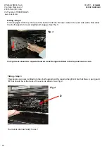
Access to the mains terminals is gained by removing the
rear access cover. The mains cable must pass through
the cable clamp adjacent to the terminal block.
Sufficient cable should be used to allow the cooker to
be pulled out for servicing.
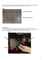
Ensure that the mains cable is routed away from any
brackets affixed to the rear panel and is not trapped to
the rear wall when pushing the cooker into position
between cabinets.
This operation must be performed by a
qualified technician.
Before moving your cooker check that it is cool, and switch off
at the cooker control unit. Movement of your cooker is
most easily achieved by lifting the front as follows:
Take care in moving the cooker as it is heavy. Take care
to ensure that any floor covering is not damaged.
Splashplate optional, apply to Parts Department (see
Back Cover for contact number.)
The following instructions should be read by a qualified
technician to ensure that the appliance is installed,
regulated and technically serviced correctly in
compliance with current regulations.
ACCESSORIES
The number and type of accessories may vary depending on which model
is purchased. Other accessories that are not supplied can be purchased
separately from the After-sales Service.
The number and type of accessories may vary depending on which model
is purchased. Other accessories that are not supplied can be purchased
separately from the After-sales Service.
ANTI-STICK TRAY
KIT GRILL PAN
When the cooker is first used an odour may be emitted,
When first using the cooker ensure that the room is well
this will cease after a period of use.
ventilated (e.g. open a window or use an extractor fan)
and that persons who may be sensitive to the odour avoid
any fumes. It is suggested that any pets be removed from
the room until the smell has ceased. This odour is due to
temporary finish on oven liners and elements and also any
moisture absorbed by the insulation.
GRID


