


Installation 27
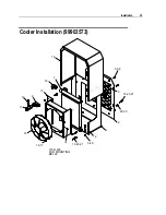
99903573 PARTS
ITEM PART #
DESCRIPTION
QUANTITY
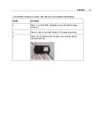
9.
72531134
ELBOW STREET STL 1X90°
1
10.
72531430
ELBOW MPT/90/JIC 1.00 16 (WAS
72534342)
1
11.
72534390
TEE #12JIC #8FPT #16MPT STL
1
12.
77041659
TEMP SWITCH, FAN
1
13.
60125752
COOLER SHROUD, HYD AUX SIDEPACK 1
14.
72061090
SCR-SELF TAP #12-24X.62 PL HEX WH
1
15. 70733880 FAN
1
16.
72060004
CAP SCR 1/4-20X1 HHGR5Z
4
17.
72062104
NUT 1/4-20 HEX NYLOC
4
18.
60125784
HYD COOLER COVER
1
19.
72063228
WASHER, NYLOC 1/4X5/8X1/16
8
20.
72063001
WASHER 1/4 FLAT
8
21.
72601652
SCR-MACH 1/4-20X3/4 TRHTORXSS
8
22.
72060025
CAP SCR 5/16-18X1 HHGR5Z
4
23.
72062109
NUT 5/16-18 HEX NYLOC
4
24.
77441094
HARNESS-AUX HYD COOLER
1
25.
72060047
CAP SCR 3/8-16X1.25 HHGR5Z
4
REV. E 20060523
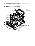
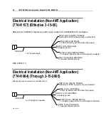
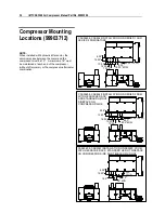
NOTE:
When the compressor is installed with a hydraulic after-cooler, the minimum space between the cooler and the
compressor must be 10". Keep at least 8” on each end of the compressor-cooler combination.
Compressor Space Requirements
CAUTION
Maintain a minimum of 8" clearance on each end of the compressor for proper airflow. If
installing the compressor with a hydraulic aftercooler, keep 10" minimum between the
compressor and cooler, while still maintaining the 8" of space on each end of the compressor
- cooler combination. Failure to follow the recommended installation guidelines will void the
warranty on the compressor.