WiMOD LR Starter Kit
Quick Start Guide
iM88x_StarterKit_QuickStartGuide.docx/
page 4 of 6
2.2
Hardware Setup
Setup of the Demo Boards
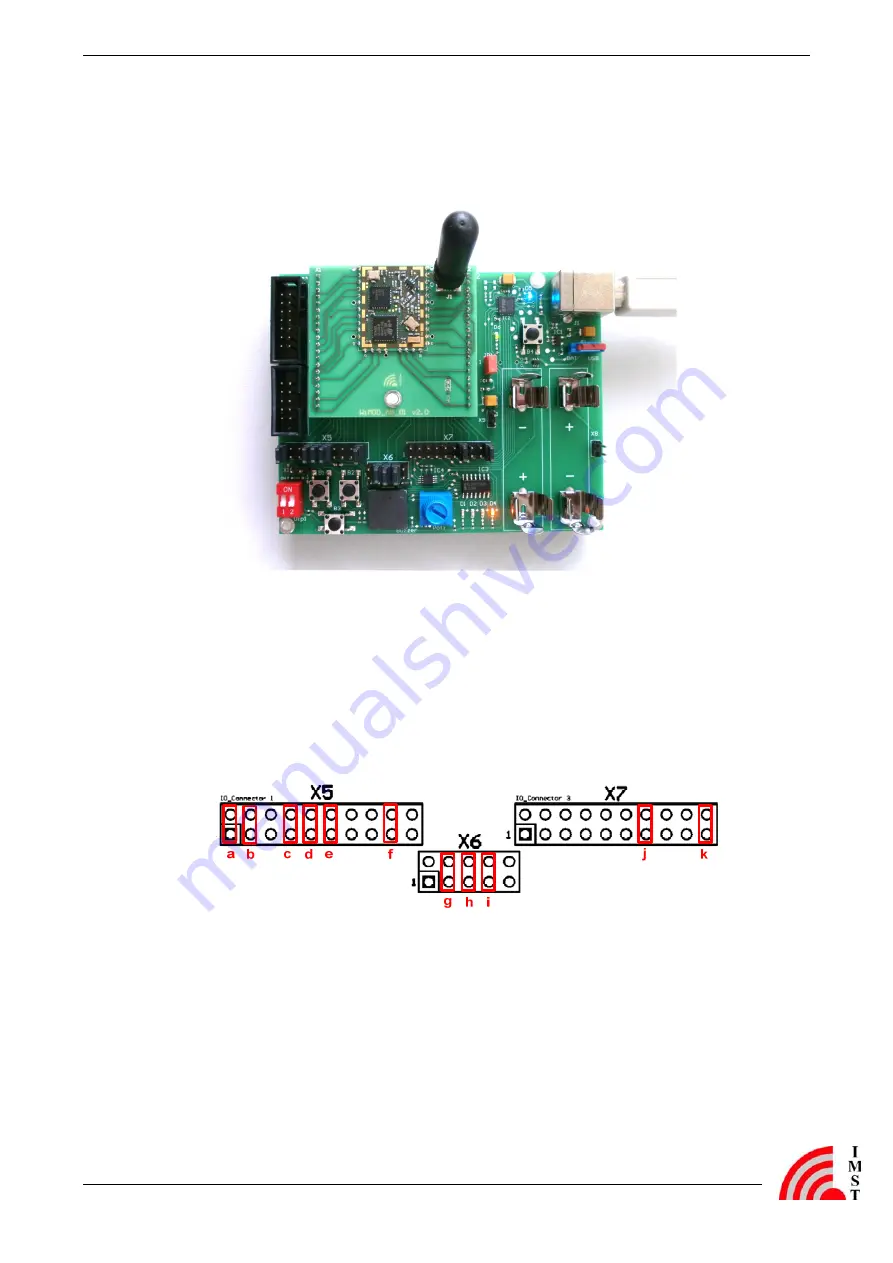
Figure 1: WiMOD LR module iM880B and Demo Board
-
Plug the adapter boards with the soldered radio module on the Demo Boards.
-
Mount the antennas on the boards.
-
Make sure that the supply voltage jumpers JP1 are set on both boards
-
Verify that the jumper configuration is equal to the default jumper setup:
Figure 2-2: Default jumper set-up
Connect the Demo Board with an USB cable to your PC and switch S1 into position “USB”. If
successful, the power LED (D6) and the USB LED (D5) are turned on. After the Demo Board is
detected by your PC as a new hardware please follow the given instructions to install the new
virtual COM port.
The orange LED (D4) indicates that the radio module is awake and ready to receive instructions
from the WiMOD LR Studio.


