background image

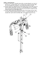
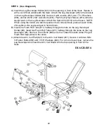
STEP 3    (See Diagram 3) 


A.) Attach the Lat Bar Frame (#23) to the Lat Bar Base (#10). Secure it with two M10 x 2 

½” Allen Bolts (#22), four 

 ¾” Washers (#5), and two M10 Aircraft Nuts (#6). 

B.) Slide the Weight Post (#31) onto the Lat Bar Frame (#23).  
C.) Slide two Rubber Bumpers (#54) onto the weight posts.  Attach two short Olympic 

Sleeves (#33) onto the posts. Secure them with two 

2” Spring Clips (#34).  

 DIAGRAM 3 


Summary of Contents for POWERHOUSE SM 3000

Page 1: ...tifier Assembly Instruction Parts List Warranty Ordering Parts Model SM 3000 Retain This Manual for Reference 06 24 02 OWNER S MANUAL POWERHOUSE SMITH MACHINE SM 3000 IMPEX FITNESS PRODUCTS 14777 DON...

Page 2: ...DUCTS For your safety and benefit read this manual carefully before using the machine As a manufacturer we are committed to provide you complete customer satisfaction If you have any questions or find...

Page 3: ...DO NOT wear robes or other clothing that could become caught in the machine Running or aerobic shoes are also required when using the machine 7 Use the machine only for its intended use as described...

Page 4: ...3...

Page 5: ...t Only finger tighten for now B Repeat the above procedure to attach the Right Base Frame 2 C Attach the Front Vertical Beam 9 to the bracket on the Left Base Frame 1 Secure it with two M10 x 2 Carria...

Page 6: ...53 D Insert the Bar through the Sliding Safety Catch 17 on the right side Place another 3 Thick Rubber Bumper 54 onto the Bar Make sure the gap on both side of the bar is even Secure the M8 x 1 2 Bolt...

Page 7: ...with two M10 x 2 Allen Bolts 22 four Washers 5 and two M10 Aircraft Nuts 6 B Slide the Weight Post 31 onto the Lat Bar Frame 23 C Slide two Rubber Bumpers 54 onto the weight posts Attach two short Ol...

Page 8: ...0 Aircraft Nut 6 B Attach the back of the Upper Frame 21 to the top of the Lat Bar Frame 23 Secure it with two M10 x 2 Allen Bolts 22 four Washers 5 and two M10 Aircraft Nuts 6 C Secure the Upper Fram...

Page 9: ...fly Pulley Support 48 to the Rear Vertical Beam 8 Secure them with two M10 x 3 Carriage Bolts 66 two Washers 5 and two M10 Aircraft Nuts 6 C Attach the Right Butterfly 41 to the Axle on the Butterfly...

Page 10: ...the Butterfly Pulley Support 48 Attach a Pulley 38 Secure it with one Pulley Fender 47 one M10 x 1 Allen Bolt 24 two Washers 5 and one M10 Aircraft Nut 6 Repeat the same procedure to attach the other...

Page 11: ...ys by installing the upper pulley to a lower hole D Pull the Cable 25 upward back to the Upper Frame 21 Install another Pulley E Draw the Cable 25 downward towards the Weight Post 31 Secure the end of...

Page 12: ...DIAGRAM 7 11...

Page 13: ...12...

Page 14: ...r Cable 1 15 Quick Release Knob 2 65 77 Butterfly Cable 1 16 Guide Rod 2 66 M10 x 3 Carriage Bolt 8 17 Sliding Safety Catch 2 67 2 x 2 End Cap 5 18 1 Bushing 4 19 Front Top Beam 1 20 2 Square End Cap...

Page 15: ...er 3 Align the holes and secure it with two M10 x 5 8 Allen Bolts 31 and Washers 39 C Slide the Sliding Block 9 onto the Incline Adjustment Bar 10 Align the holes then thread in a Knob Lock 20 to hold...

Page 16: ...me 6 Align the holes and secure them with one M10 x 1 5 8 Allen Bolt 32 and one Washer 39 Repeat the same procedure to install the other side C Attach the two Backrest Supports 7 to the pivot on the M...

Page 17: ...EP 3 See Diagram 3 A Align the holes on the two Backrest Supports 7 to the pivot on the Sliding Block 9 Secure them with one M10 x 6 Allen Bolt 35 two Washers 39 and one M10 Aircraft Nut 41 DIAGRAM 3...

Page 18: ...9 and one M10 Aircraft Nut 41 Do not over tighten the nut and bolt The Bracket needs to be able to swivel Attach two bushings 23 to the pivot on the Seat Incline Support Bracket 8 B Attach the Seat Su...

Page 19: ...eat Support Frames 6 Align the holes and secure it with four M8 x 2 Allen Bolts 37 and 5 8 Washers 40 B Place the Backrest Board 15 onto the Backrest Supports 7 Align the holes and secure it with four...

Page 20: ...ch at a decline position to do Ab exercises place at least 30 lbs of weights on the leg developer to hold it down B Insert one Foam Roll Tube 11 halfway through the hole on the Leg Developer Holder 4...

Page 21: ...20...

Page 22: ...16 Leg Developer Bushing 2 17 Arm Curl Stand 1 18 1 x 3 Rubber Pad 1 19 Spring Clip 1 20 Knob Lock 2 21 Arm Curl Pad 1 23 Foam Roll End Cap 6 23 Bushing 14 24 1 End Cap 1 25 2 Square Sleeve 1 26 1 Squ...

Page 23: ...or other damages with respect to any economic loss loss of property loss of revenues or profits loss of enjoyments or use costs of removal installation or other consequential damages or whatsoever na...

Reviews: