©
IMPEX INC. www.impex-fitness.com
7
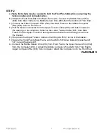
STEP 2
A.)
Note: Extra help may be needed to hold the Front Post (#4) while connecting the
tension cables and computer wires.
B.) Attach the Front Post (#9) to the Main Frame (#1). Connect the Middle Sensor Wire
(#34) from Main Frame to the Middle Sensor Wire (#33) from the bottom of Front Post.
C.) Connect the Lower Computer Wire (#22) from Main Frame to the Middle Computer
Wire (#23) from the Front Post.
D.) Pull the tension connector from the Upper Tension Cable (#16) and slide in between
the opening on the connector holder on the Lower Tension Cable (#21) from Main
Frame. Pull the Upper Tension Cable Upward and slide the wire through the slot on
the bracket.
E.) Drop down the Upper Tension Cable so the fitting sits firmly on top of the bracket.
F.) Secure the Front Post to Main Frame with four M8 x 5/8” Allen Bolts (#24) and four Ø
5/8” Curved Washers (#7).
G.) Connect the Middle Sensor Wire (#33) from Front Post to the Upper Sensor Wire (#32)
from the Computer (#10). Connect the Middle Computer Wire (#23) from Front Post to
Upper Computer Wire (#31) from Computer. Attach the Computer on to the Front Post.
DIAGRAM 2


