background image

© Impex Inc.                                                                                                                                        www.marcypro.com 


TABLE OF CONTENTS 


BEFORE YOU BEGIN 

 
Thank you for selecting MARCY MAGNETIC UPRIGHT BIKE ME-
1016U by IMPEX

®

 INC. For your safety and benefit, read this manual 

carefully before using the equipment. As a manufacturer, we are 
committed to providing you with complete customer satisfaction. If you 
have any questions, or find there are missing or damaged parts, we 
guarantee you complete satisfaction through direct assistance from our 
factory. To avoid unnecessary delays, 

please call our TOLL-FREE


customer service number

. Our Customer Service Agents will provide 

immediate assistance. 


Toll-Free Customer Service Number 

1-800-999-8899 

Mon. 

– Fri. 9 a.m. – 5 p.m. PST 

www.marcypro.com


[email protected]


BEFORE YOU BEGIN 

IMPORTANT SAFETY NOTICES 

CARE AND MAINTENANCE 

WARNING LABEL PLACEMENT 

HARDWARE PACK 

COMPONENTS 

ASSEMBLY INSTRUCTIONS 

EXPLODED DIAGRAM 

12 

PARTS LIST 

14 

COMPUTER INSTRUCTIONS 

15 

EXERCISE GUIDELINES 

16 

WARRANTY 

18 

ORDERING PARTS 

18 

Summary of Contents for MARCY ME-1016U

Page 1: ...re and Maintenance Parts List Warranty Ordering Parts Model ME 1016U Retain This Manual for Reference 180501 OWNER S MANUAL MAGNETIC UPRIGHT BIKE ME 1016U IMPORTANT Please read this manual before comm...

Page 2: ...ee you complete satisfaction through direct assistance from our factory To avoid unnecessary delays please call our TOLL FREE customer service number Our Customer Service Agents will provide immediate...

Page 3: ...ol or drugs 12 While keeping the head erect focus eyes on the equipment toward the perimeter 13 Before exercising always do stretching exercises to properly warm up 14 If the user experience dizziness...

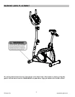
Page 4: ...ARNING LABEL PLACEMENT The warning labels shown here have been placed on the Base Frame If the labels are missing or illegible please call customer service at 1 800 999 8899 for replacements Apply the...

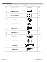
Page 5: ...drawn to scale Please use your own ruler to measure the size No Description DRAWING Q ty 6 Carriage Bolt M10x3 4 7 Curved Washer 4 8 Domed Nut 4 11 Quick Release Knob 1 17 Allen Bolt M8x 4 27 Decorat...

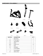
Page 6: ...1 1 NO 22 NO 18 NO 19 NO 15 NO 9 3 2 NO 10 NO 41 NO 16 NO 3 NO 2 PART NO DESCRIPTION Q TY 1 Main frame 1 22 Front support 1 15 Seat support 1 18 Meter 1 9 10 Pedal L R 1 1 16 Seat 1 19 Handlebar 1 3 F...

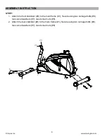
Page 7: ...front stabilizer 3 to the main frame 1 Secure using two carriage bolts 6 two curved washers 7 two domed nuts 8 2 Attach the rear stabilizer 2 to the main frame 1 Secure using two carriage bolts 6 two...

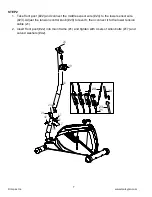
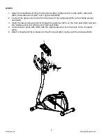
Page 8: ...ensor wire 24 to the lower sensor wire 23 Adjust the tension control knob 20 to level 8 then connect it to the lower tension cable 21 2 Insert front post 22 into main frame 1 and tighten with 4 sets o...

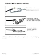
Page 9: ...en the opening on the wire holder on sensor wire Connector Pull the extension sensor wire Connector backward and slide the wire through the slot on the bracket Drop down the Connector so the fitting s...

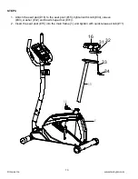
Page 10: ...from the back of the computer 18 to the middle sensor wire 24 3 Insert the lower pulse wire 43 through the grommet 75 on the front post 22 and pull the middle sensor wire 43 out of front post 22 4 Con...

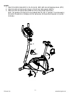
Page 11: ...m STEP 4 1 Attach the seat pad 16 to the seat post 15 tighten with knob 34 sleeve 33 washer 32 and bowl shaped nut 31 2 Insert the seat post 15 into the main frame 1 and tighten with quick release kno...

Page 12: ...the left and right pedal straps to the left and right pedals 9 10 3 Attach the left and right pedals 9 10 to the left and right crank arms Note The pedals and crank arms are marked with R and L stick...

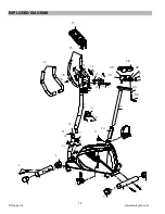
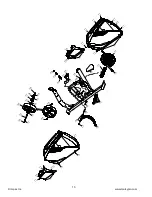
Page 13: ...12 Impex Inc www marcypro com EXPLODED DIAGRAM 15 1 2 3 6 6 5 5 21 23 25 26 27 28 20 22 18 6 4 4 42 7 17 17 8 7 8 7 8 7 8 9 10 11 24 19 35 36 37 39 38 40 43 70 16 30 31 33 34 12 13 14 32 41 42 42 75...

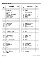
Page 14: ...om 6 9 5 0 5 0 5 1 4 4 4 5 4 5 4 6 4 7 4 5 4 8 4 9 5 6 5 3 5 4 5 4 5 5 5 2 5 7 5 9 6 0 6 4 2 6 6 6 6 7 6 8 6 9 1 2 1 4 1 4 7 2 7 3 7 4 L 7 0 7 0 7 0 7 0 7 4 R 7 1 7 1 7 1 7 1 7 1 7 0 5 8 6 3 6 2 6 1 7...

Page 15: ...t Post 1 53 Crank 1 16 Seat 1 54 Ball Bearing assembly 1 17 Allen Bolt M8x 4 55 Pulley 1 18 Computer 1 56 Flywheel 1 19 Handlebar 1 57 Idler Assembly 1 20 Tension control w upper cable wire 1 58 Belt...

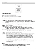
Page 16: ...e total calories of exercise from start to end 2 Press MODE button unit CAL appears Press SET button to set exercise calories When the set is zero the computer will sound an alarm for 15 seconds 6 ODO...

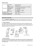
Page 17: ...se weight 1 The Warm Up Phase This stage helps get the blood flowing around the body and the muscles working properly It will also reduce the risk of cramp and muscle injury It is advisable to do a fe...

Page 18: ...the week MUSCLE TONING To tone muscle while on your Magnetic Upright Bike you will need to have the resistance set quite high This will put more strain on our leg muscles and may mean you cannot train...

Page 19: ...rformance of the product or other damages with respect to any economic loss loss of property loss of revenues or profits loss of enjoyments or use costs of removal installation or other consequential...

Reviews: