Impex I-Control Manual Download Page 35


I-Control manual


page 34 


I-Control software update 


The I-Control software can easily be updated if necessary.  To update, a micro Sd memory card is required. The Sd 
card must be FAT16 or FAT32 formatted. The capacity of the Sd card can be up to 32GB.


Updating the I-Control is as follows: 
 

1


Using your PC, copy the update file to the micro Sd 
card. The file should be placed in the root directory and 
not in a folder on the Sd card. 

2


Make sure there is no backup file from any previous 
backup on the Sd card. Delete any previous backup 
files, which are those with .BCK and .USED extensions. 

3


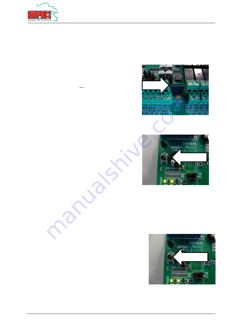
Insert the Sd card into the connector. See upper 
picture. 

4


Press the SW1 button located on the bottom printboard 
of the I-Control. See lower picture. 

5


The I-control writes all the set functions on the Sd card,                                                                           
which is indicated by the flashing ADDR-led.  

6


Thereafter, the I-control starts the boot program and 
the update is performed. The display will show this 
process.  

7


Once the update is completed, the user program 
automatically starts.  

8


Thereafter, the functions saved on the Sd card are 
replaced in the relevant functions. Any "new" features 
in the new software will be set to the default. 

9


The I-control is updated and ready for use.  


Restoring factory settings 


To reset the settings to the factory settings, proceed as follows: 
 

1


Turn off the power. 

2


Press the SW1 button on the bottom printboard and keep it 
pressed while the power is turned on.  

3


Keep this button pressed for at least 30 seconds until the 
run-indicator blinks at one second intervals.      

4


The factory settings are now restored.                 


Sd-card 

SW1 button 

SW1 button 

Summary of Contents for I-Control

Page 1: ...IMPEX BARNEVELD BV I Control Manual Edition 1 01 N 13 00 60000...

Page 2: ...derived from this manual In the context of continuous development and improvement Impex Barneveld BV retains the right to modify this manual without prior notice Any reproduction is prohibited without...

Page 3: ...ooling Do not turn the power off even when the poultry house is empty Do not use water to clean the I Control The I Control is splash proof not water proof A damaged or defective I Control is dangerou...

Page 4: ...nding installer program 18 Connection diagrams 19 Electrical connection diagram 19 Flush valve connection diagram 24V internal power supply 20 Flush valve connection diagram External power supply 21 1...

Page 5: ...ead all settings The main screen gives a summary of the I Control status such as which flushing group is active flushing times etc To change the settings the I Control has a keyboard The numeric keys...

Page 6: ...ushing starts by the temperature control when the temperature of the water becomes too high Dirt on Flushing dirt The flushing starts by the pollution control when the drinking water becomes too pollu...

Page 7: ...tcut 5 STOP The following screen is displayed You can choose to stop the I Control completely house is empty or stop temporarily I Control compete stop Press the ENTER key and the I Control will stop...

Page 8: ...Note 1 Functions showing a measurement such as a measured temperature can neither be selected nor adjusted Note 2 Dependent on the settings of the installer s program some menus and or functions are n...

Page 9: ...ally starts flushing at the programmed time or when drinking water pollution is detected Te Dir Temperature dirt The I Control automatically starts flushing based on temperature or pollution detection...

Page 10: ...start time set the timer to 00 00 hours The start time will then be ignored Note When the I Control is still in the waiting time after the last flushing a start time will be skipped over Rep day st 1...

Page 11: ...menu Start flushing 1 to 100 If pollution exceeds a preset value flushing will start automatically Note Dependent on the settings set by the installer this function may not be displayed Max flushing 1...

Page 12: ...given number of days There are 4 start times When set at 1 the start time is every day 2 every 2 days 3 every 3 days etc The start settings 2 to 4 can be set the same way Time Date Select this menu by...

Page 13: ...the amount of water in which the specified amount of medicine is to be dissolved This will be added to the drinking water by the medicine pump Filling water pipes Select this menu by pressing the key...

Page 14: ...options are English and Dutch with additional languages to be added in the future No of valves 1 to 10 valves This function specifies how many flush groups will be are used The main screen for the use...

Page 15: ...omputer Determine whether a NO or NC relay is used The main solenoid valve voltage must be originate from the main computer 0 remains connected Note the same transformer or phase is necessary When usi...

Page 16: ...s the voltage coming from the pollution sensor where 100 pollution must be indicated The reading is divided linearly between the two set input voltages Note This function is only meaningful if the ana...

Page 17: ...ater system is defective ALARM This alarm activates an external alarm device when water sensor failure occurs WARN This alarm is displayed only as information Supply sens alarm warn With this function...

Page 18: ...connected to GND therefore no is water detected Water press off on This is the status of the digital input for water pressure detection by a pressure switch OFF The digital input is not connected to G...

Page 19: ...rd curves are pre set the default setting is 2 minutes Standard curve 1 LAYING HENS Standard curve 2 REARING Standard curve 3 BROILERS LAYING HENS Every morning at 4 30 hours 2 minutes of flushing wit...

Page 20: ...66 Zero supply voltage Note It is possible to use 115VAC as well as 230VAC voltage Set the switch to the desired voltage Caution If the incorrect voltage is selected the I Control can be irreparably...

Page 21: ...50 Flush valve 6 51 52 Flush valve 7 53 54 Flush valve 8 55 56 Flush valve 9 57 58 Flush valve 10 Note The flush valves must be 24VAC with a maximal 6VA electric load Important The 4 jumpers with the...

Page 22: ...be in EXT position See diagram Note An external power supply may be needed if the internal power supply has insufficient power or if another valve voltage other than 24VAC is desired Note The maximum...

Page 23: ...15V 230V main valve connection diagram I Control 63 64 Main valve relay Potential free max 230VAC 2 Amp Note The relay is potential free A 230V connection has to be made See diagram Note The maximum r...

Page 24: ...ntial free maximum 230VAC 2 Amp 23 37 24VAC Main valve power supply 24VAC maximum 18VA Note The relay is potential free A 230V connection has to be made See diagram Note The maximum relay load is 230V...

Page 25: ...ion diagram N o relay external computer 63 64 Main valve relay Potential free maximum 230VAC 2Amp Note The relay is potential free and must be connected parallel to the relay of the external computer...

Page 26: ...ion diagram N c relay external computer 63 64 Main valve relay Potential free maximum 230VAC 2Amp Note The relay is potential free and must be series connected with the relay of the external computer...

Page 27: ...nking water circuit temperature sensor 33 GND 20 34 Water supply temperature sensor 34 GND Important The corresponding jumpers must be in TEMP position See diagram Note Always use shielded cable with...

Page 28: ...to external climate computer Potential free maximum 24VAC DC 100 mA Note Always use shielded cable with a minimum diameter of 0 8 mm for the liter counter and connect the shield to the GND terminal No...

Page 29: ...imum 50 mA 13 27 GND power supply Note Always use shielded cable with a minimum diameter of 0 8 mm for the dirty water sensor and connect the shield to the GND terminal Note The 12V or 24V power suppl...

Page 30: ...mportant The jumper of the 0 10V input must be in VOLT position See diagram Note Always use shielded cable with a minimum diameter of 0 8 mm for the dirty water sensor and connect the shield to the GN...

Page 31: ...50 mA 13 27 GND power supply Note Always use shielded cable with a minimum diameter of 0 8 mm for the pressure switch sensor and connect the shield to the GND terminal Note The 12V or 24V power supply...

Page 32: ...50 mA 13 27 GND power supply Note Always use shielded cable with a minimum diameter of 0 8 mm for the water detection sensor and connect the shield to the GND terminal Note The 12V or 24V power supply...

Page 33: ...free maximum 24VAC DC 2 Amp Note Contacts 59 60 are closed when there is no alarm relay is active When there is an alarm contacts 59 60 will be disconnected relay is inactive Note The alarm has a watc...

Page 34: ...01217 Primabel tubing 5 mtr 7 Drain pipe minimal 50 mm 8 Connection Primabel tubing and drain pipe The installation of the drain pipe and the connection of the Primabel tubing to the drain pipe has to...

Page 35: ...I Control See lower picture 5 The I control writes all the set functions on the Sd card which is indicated by the flashing ADDR led 6 Thereafter the I control starts the boot program and the update i...

Page 36: ...z Power consumption Max 30 VA Primary fuse T2A Power supply for sensors 24V DC max 50 mA 12V DC max 50 mA Temperature inputs 2 Measuring range temperature inputs 70 0 C to 130 0 C Alarm relay with wat...

Reviews: