background image

© IMPEX INC.                                                                                                                                 

www.marcypro.com


TABLE OF CONTENTS


BEFORE YOU  BEGIN 


Thank you for selecting the CIRCUIT FITNESS Magnetic Resistance Upright Bike by 

IMPEX

®

 INC. For your safety and benefit, read this manual carefully before using the 

bike.  As  a manufacturer, we are committed to provide you complete customer 

satisfaction. If you have any questions, or find there are missing or damaged parts, 

we guarantee you complete satisfaction through direct assistance from our factory. To 

avoid unnecessary delays, 

please call our TOLL-FREE customer service number. 

Our 

Customer Service Agents will provide immediate assistance to you. 


BEFORE YOU BEGIN 

IMPORTANT SAFETY NOTICES 

WARNING LABEL PLACEMENT 

HARDWARE PACK 

COMPONENT FOR ASSEMBLY 

IMPORTANT ASSEMBLY INSTRUCTION 

EXPLODED DIAGRAM 

11 

PARTS LIST 

12 

CARE AND MAINTENANCE, WEIGHT CAPACITY & DIMS. 

13 

COMPUTER 

14 

EXERCISE GUIDELINES 

19 

WARRANTY 

21 

ORDERING PARTS 

21 

Toll-Free Customer Service Number       

1-800-999-8899 

Mon. - Fri. 9 a.m. - 5 p.m.  PST 

www.marcypro.com


[email protected]


Summary of Contents for CIRCUIT FITNESS AMZ-594U

Page 1: ...ware Pack Assembly Instruction Parts List Warranty Ordering Parts Model AMZ 594U Retain This Manual for Reference 190701 ASSEMBLY OWNER S MANUAL Magnetic Resistance Upright Bike AMZ 594U IMPEX INC 280...

Page 2: ...satisfaction through direct assistance from our factory To avoid unnecessary delays please call our TOLL FREE customer service number Our Customer Service Agents will provide immediate assistance to y...

Page 3: ...quired when using the machine 7 Use the machine only for its intended use as described in this manual DO NOT use attachments not recommended by the manufacturer 8 Do not place any sharp object around...

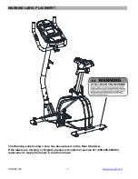
Page 4: ...WARNING LABEL PLACEMENT The Warning Labels shown here has been placed on the Rear Stabilizer If the labels are missing or illegible please call customer service at 1 800 999 8899 for replacement Apply...

Page 5: ...are not drawn to scale Please use your own ruler to measure the size NO Description Qty Drawings 6 Allen Bolt M8 2 4 7 Curved Washer 8x 8 8 Spring washer 4 11 Quick Release Knob 1 17 Allen Bolt M8x 4...

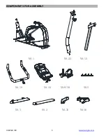
Page 6: ...IMPEX INC www marcypro com 5 COMPONENTS FOR ASSEMBLY NO 1 NO 22 NO 18 NO 19 NO 15 NO 9 10 NO 16 NO 3 NO 2 NO 5 NO 31...

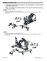
Page 7: ...machine to avoid possible injury STEP 1 1 Thread the Stopper 5 to the Front Stabilizer 3 2 Attach the Front Stabilizer 3 to the main frame with two Allen bolts 6 Curved washers 7 Locking Washers 8 7 8...

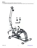
Page 8: ...INC www marcypro com 7 STEP 3 1 Connect Lower sensor wire 23 to Upper sensor wire 24 2 Insert the Front Post 22 into the main frame secure with Allen bolts 17 and Curved washers 7 7 17 7 17 7 17 23 24...

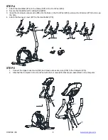
Page 9: ...re 38 into the hole on the Front Post 22 and use the Grommet 13 to close up the hole 4 Attach the Recovery cover 27 to the Handle Bar 19 19 28 27 38 13 25 13 38 28 27 STEP 5 1 Connect the Upper sensor...

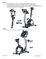
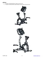
Page 10: ...e the bolt from two sides 3 Insert the Seat Post 15 to the opening on the Main Frame 1 Thread the Quick Release Knob 11 through the hole on Seat Post 15 to securely lock it at desired height When adju...

Page 11: ...IMPEX INC www marcypro com 10 STEP 8 1 Thread the Right Pedal 10 clockwise into the Crank 2 Thread the Left Pedal 9 counterclockwise into the crank on the other side 10 9...

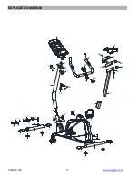
Page 12: ...IMPEX INC www marcypro com 11 EXPLODED DIAGRAM 2 3 4 4 4 4 7 17 17 7 7 18 22 11 37 10 9 24 5 5 5 5 20 20 8 6 7 8 6 7 21 21 21 21 26 14 26 23 19 28 27 15 16 33 13 14 31 30 12 34 32 36 1 35 36 25 38...

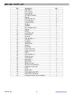
Page 13: ...craft Nut M8 2 15 Seat Support 1 16 Seat Pad 1 17 Allen Bolt M8 x 4 18 Computer 1 19 Handlebar 1 20 Rolling wheel 2 21 Bearing 4 22 Front Post 1 23 Lower sensor wire 1 24 Upper sensor wire 1 25 Clamp...

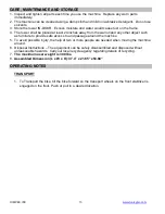
Page 14: ...r object such as furniture to provide safe access to and passage around the machine 5 To avoid possible injury the help of two or more people are needed when moving the machine around 6 Disposal Instr...

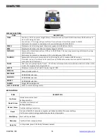
Page 15: ...ies This data is a only for reference for comparison of different exercise sessions and SHOULD NOT be used in medical treatment PULSE User may set up target pulse from 0 30 to 230 and computer buzzer...

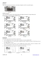
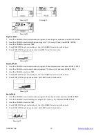
Page 16: ...nual Mode Press START in main menu may start workout in manual mode 1 Use UP or DOWN Arrow to select workout program choose Manual and press MODE ENTER 2 Use UP or DOWN Arrow to set TIME Drawing 8 DIS...

Page 17: ...ram choose Advance mode and press MODE ENTER 2 Use UP or DOWN Arrow to select Advance program 1 4 Drawing 14 and press MODE ENTER 3 Use UP or DOWN Arrow to set TIME 4 Press START STOP key to start wor...

Page 18: ...rcising for a period keep holding on hand grips or wearing chest strap and press RECOVERY key All function display will stop except TIME starts counting down from 00 60 to 00 00 Drawing 19 Screen will...

Page 19: ...nd BMI result is below 5 or exceeds 50 Drawing 26 Drawing 21 Drawing 22 Drawing 23 Drawing 24 Drawing 25 Drawing 26 Noted 1 After 4 minutes without pedaling or pulse input console will enter into powe...

Page 20: ...ses as shown below Each stretch should be held for approximately 30 seconds do not force or jerk your muscles into a stretch if it hurts STOP 2 The Exercise Phase This is the stage where you put the e...

Page 21: ...your MAGNETIC ROWER you will need to have the resistance set quite high This will put more strain on our leg muscles and may mean you cannot train for as long as you would like If you are also trying...

Page 22: ...rformance of the product or other damages with respect to any economic loss loss of property loss of revenues or profits loss of enjoyments or use costs of removal installation or other consequential...

Reviews: