background image

IMP Series User’s Manual 


2.0 Getting Started 


The IMP is a well design compact portable computing machine that is 
both  nimble  as  well  as  rugged.    It will serve your needs for both 
expansion as well as performance.  An important aspect of the IMP is 
the concept of standardizations, which means all components that 
you can find off the shelf or proprietary designed will fit into the IMP.  If 
the peripheral is designed according to industry standard for 
interconnectivity then it will fit.  With that in mind, we will layout and 
identify each of the component. In this section you can find each 
component of the IMP with respect to its purpose and usage.  


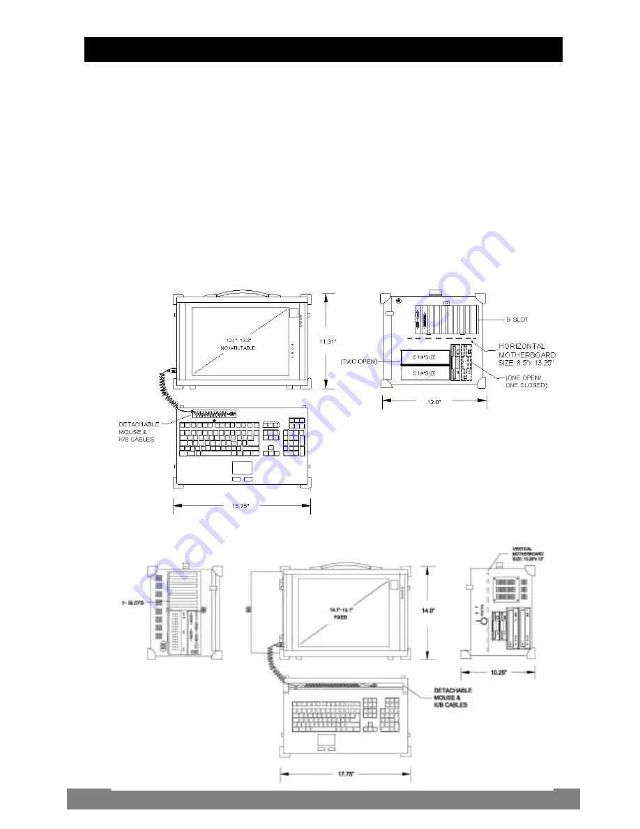
IMP 600 


IMP 670 

2.0 Getting Started


Summary of Contents for -600 Series

Page 1: ...e IMP 5 4 0 Computer Operation 8 5 0 Hardware installation 14 5 1 I l l u s t r a t i o n f o r I M P 6 0 0 1 4 5 2 I l l u s t r a t i o n f o r I M P 6 7 0 2 0 6 0 Software installation 28 7 0 Maint...

Page 2: ...6MB ATI M6 chipset AGP card with 64MB Analog to digital conversion board ATI M6 D C with 64MB Video RAM Keyboard Mouse 108 keys multi languages touchpad Case Size 15 75 x12 x11 31 400 x305 x 287mm 17...

Page 3: ...oftware and operating systems It has more computing power than that of most desktops and traditional portable computers Its full size add in slots Pentium 4 processing power and a XGA resolution TFT c...

Page 4: ...P is the concept of standardizations which means all components that you can find off the shelf or proprietary designed will fit into the IMP If the peripheral is designed according to industry standa...

Page 5: ...IMP Series User s Manual Drive Bays IMP 600 with 2 x 5 25 open bays 1x 3 5 open bays IMP 670 with 2 x 5 25 open bays 2 x 3 5 open bays 3 0 Feature of the IMP series serserFeatures of the...

Page 6: ...f 1024 768 or 1280 1024 for 14 15 Speaker Integrated two speakers built in allow media audio play back without having to outsource attachment Speaker has volume control for different environment usage...

Page 7: ...O opening for protection of vital equipment inside it serves to detour object from entering as well as cooling drilled opening Handle Large handle provide convenient transportation of the portable wi...

Page 8: ...The keyboard now can then be removed for usage How to close keyboard Closing the keyboard back onto the portable follows the same procedure as opening in a reverse manner It is noted that the keyboar...

Page 9: ...function and shortcut keys Keyboard position You may want to adjust the keyboard angle by folding the top portion of the keyboard or just taking off the main case TOUCHPAD operation TOUCHPAD surface c...

Page 10: ...ng power plug is supplied Depending on your Power supply type you may find a main power switch located next to the power receptacle and the position of the switch is of the following O Off I On This i...

Page 11: ...nected the display should come on if the machine is powered on The signal is standard with the internal viewing resolution and the default setting is simultaneous display both on portable s LCD and CR...

Page 12: ...rage capacity CD is read only media a CDR or CDRW are medium that are for user creation of data on CD medium and is pre loaded with data You may open the CD ROM drive door by pushing the eject button...

Page 13: ...may provide better angle for operating 4 9 VGA Based on your model you may have either 1 16MB ATIM3 2x AGP with special backplane 2 64MB ATIM6 4x AGP with special backplane 3 A D Conversion Board 4 On...

Page 14: ...of installation and compatibility feature of any upgrade And understand the concept of electrostatic damage that can occur during handling of sensitive electronic equipments proper precaution should...

Page 15: ...IMP Series User s Manual 3 Remove stabilizer bars 4 Remove the inner chassis Please remove the sound adjust board before taking off the inner chassis Screw Unscrew Slide Out Unscrew...

Page 16: ...IMP Series User s Manual 5 Remove drive bay housing 6 Insert system board mounting standoff Standoff Standoff Standoff Standoff Standoff Standof Standof Standoff Bottom Screw x 4...

Page 17: ...em board manual for detail references 8 Connect keyboard and touchpad cables Please refer to your system board manual for detail references 9 Connect power LED and speaker wires Please refer to System...

Page 18: ...IMP Series User s Manual 11 Install HDD into Drive bay housing 12 Install CDROM into drive bay housing FDD Drive HDD...

Page 19: ...IMP Series User s Manual Off Reinsert Reinsert Reinsert 13 Connect IDE and power cables 14 Reinsert stabilizer bars 15 Close back cover VGA card wire LCD on off wire Reinsert Slide...

Page 20: ...ompatibility feature of any upgrade And understand the concept of electrostatic damage that can occur during handling of sensitive electronic equipments proper precaution should be taken before procee...

Page 21: ...IMP Series User s Manual 3 Remove stabilizer bars 4 Remove drive bay housing Screw Screw Screw Screw Screw Bottom Screw x 4...

Page 22: ...IMP Series User s Manual 5 Remove power supply 6 Insert system board mounting standoff Standoff Standoff Standoff Standoff Standoff Standof Standof Standoff Bottom Screw 4 Side Screw x 4...

Page 23: ...to your system board manual for detail references 7 Install system board with CPU and RAM Please refer to your system board manual for detail references 8 Connect keyboard and TOUCHPAD cables Cables P...

Page 24: ...for detail references 9 Connect power LED and speaker wires 10 Install HDD FDD and CD ROM into housing Power wires LED wires Speaker wires Please refer to System Board Manual for actual Location CD RO...

Page 25: ...ing be the horizontal position please screw these components to the other side 11 Install drive bay housing Into chassis 12 Choosing the appropriate housing frame Side Screw x 2 Side Screw x 2 Same as...

Page 26: ...IMP Series User s Manual Vertical Horizontal 13 Install power supply Into chassis 14 Connect IDE and power cables IDE cable Power cable Under Drive Bay Bottom Screw x 4 Bottom Screw x 4...

Page 27: ...efer to your model s removal process for reinstallation 15 Install VGA card LCD ON OFF wire 16 Reinsert stabilizer bars 18 Close back cover VGA card LCD on off wire Reinsert Reinsert Reinsert Reinsert...

Page 28: ...rface environment As in the IMP a copy of the Windows NT 4 0 Workstation is pre installed in the machine Other O S description Many other operating systems are available in the market such as Linux Wi...

Page 29: ...the power cord is in top condition before using them with the IMP Make sure your power source is reliable and of proper standard The IMP power supply is capable of handling 100 240V and 50 60Hz Do no...

Page 30: ...7 8 Cleaning Fan Filter 1 Remove the filter from its housing 2 Use a compress air cleaner to blow off the dust from the filter 3 If necessary you can wash the filter material but do remember to dry it...

Page 31: ...il you get the desire result 8 2 BIOS Beep Code The BIOS beep code indicates error in system initialization The BIOS of the system board will associate with video and memory error Please check your vi...

Page 32: ...ed to the side I O PS 2 port 8 7 TOUCHPAD fails 1 Make sure the keyboard plug is inserted completely into the portable 2 If you have an external PS 2 mouse hook up on the side I O PS 2 port the touch...

Page 33: ...on 110 Power Cord 220 Power Card Option 1 1 5 Screw Pack stabilizer Screw Pack stabilizer 1 1 6 Stabilizer Supports Pack Stabilizer Supports Pack 1 1 7 Hardware Pack system 1 1 8 Ports Label Sticker 1...

Page 34: ...IMP Series User s Manual...

Reviews: