Slew Drives
Installation and commissioning
34
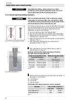
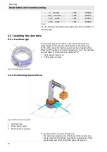
Fig. 24: Measurement setup
1
Dial gauge
2
Upper mounting structure
3
Slew Drive
4
Lower mounting structure
Procedure:
Tilting clearance measurement
1.
Switch off the system and safeguard it from being turned on
again.
2.
Permanently mark the measuring point in the main load
direction on the housing and on the bearing ring.
3.
Attach the dial gauge as shown in Fig. 24.
4.
Apply defined tilt torque, at least 50% of max. operating load,
in direction "A".
5.
Set dial gauge to zero.
6.
Apply defined tilt torque, at least 50% of max. operating load,
in direction "B".
The displayed measured value m1 corresponds to the existing
tilting clearance and serves as the base value that will be used
for comparison in later inspections.
7.
Log and document all measured values.
All inspections at a later point in time must be executed on the
same measuring point, with the same loads, at the same
relative position of the bearing rings, and in the same
sequence.
At pure axial or radial load check the tilting clearance by
applying an additional tilting load.
5.3.5
Determining the circumferential backlash
Toothing wear causes increased circumferential backlash.
Consequently it is necessary to check circumferential backlash in
accordance with the maintenance intervals (
section 6.3
"Maintenance schedule").
IMPORTANT
Do not exceed the specified values for the circumferential
backlash angle of the worm shaft (
Tab. 18). Exceeding
the specified values may result in failure of the slew drive
and damage to the connecting components.
1.
Switch off the system and safeguard it from being restarted.
2.
Determine the measuring point in the main load-carrying zone,
both on the housing as well as on the worm gear or on the
toothed ring and permanently mark these points.


