31
In case of ΔT > 35 °C, the boiler lowers the
power to avoid surpassing that value. When
this status is on, the flow temperature symbol
flashes.
3.8 CONTROL FUNCTION AIR FLOW
RATE.
With ignition request, before the start of the fan,
the condition of the pressure switch contact is ve-
rified. If this is detected closed, the continuation
of the cycle is prevented.
After a delay time of about 50 seconds, there is
a permanent block and fault “0A4” is signalled.
If the detected contact is open, the fan activates
at the “air pressure switch control” speed (3300
rpm). When the pressure switch is closed, the fan
switches to the ignition speed, and the ignition
cycle continues ignoring the pressure switch
condition.
If during operation at the “air pressure switch
control” speed (3300 rpm) the pressure switch
does not close, after a time of about 50 seconds
there is a permanent block and the fault “0A4”
is signalled.
3.9 PROGRAMMING THE BOILER P.C.B.
The boiler is prepared for possible programming
of several operation parameters. By modifying
these parameters as described below, the boiler
can be adapted according to specific needs.
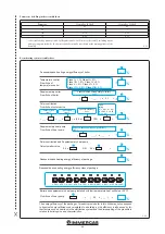
- Access programming by pressing and holding
down buttons “B” and “C”.
3-3
3.7 TROUBLESHOOTING.
N.B.:
maintenance interventions must be carried
out by an authorised company (e.g. Immergas
After-Sales Technical Assistance Service).
- Smell of gas. Caused by leakage from gas circuit
pipelines. Check sealing efficiency of gas intake
circuit.
- Repeated ignition blocks. No gas, check the
presence of pressure in the network and that
the gas adduction valve is open. Incorrect
adjustment of the gas valve, check the correct
calibration of the gas valve.
- Irregular combustion or noisiness. It may be
caused by: a dirty burner, incorrect combustion
parameters, intake-exhaust terminal not cor-
rectly installed. Clean the above components
and ensure correct installation of the terminal,
check correct setting of the gas valve (Off-Set
setting) and correct percentage of CO
2
in flue
gases.
- The over temperature safety thermostat, the
flow probe or the return probe are triggered
frequently. It can depend on the lack of water in
the boiler, little water circulation in the system
or blocked pump. Check on the manometer
that the system pressure is within established
limits. Check that the radiator valves are not
closed and also the functionality of the pump.
In addition:
- check that the exchanger safety thermostat
has not intervened. If it has, check the integrity
of the module and ceramic fibre panel, replace
the cover gasket of the manifold and reset the
thermostat by pressing the specific button.
- check that the exchanger safety thermostat
has not intervened. If it has, check the integrity
of the module and ceramic fibre panel, replace
the cover gasket of the manifold and reset the
thermostat by pressing the specific button
Also check the integrity of the thermofuse, and
if it has been triggered it will be necessary
to check the integrity of the module and the
flue circuit.
- Drain trap clogged. This may be caused by
dirt or combustion products deposited inside.
Check, by means of the condensate drain cap,
that there are no residues of material blocking
the flow of condensate.
- Heat exchanger clogged. This may be caused by
the trap being blocked. Check, by means of the
condensate drain cap, that there are no residues
of material blocking the flow of condensate.
- Noise due to air in the system. Check opening
of the special air vent valve cap (Fig. 1-25 Ref.
23). Check that system filling and air bleeding
has been performed according to the require-
ments.
- Noise due to air inside the condensation
module. Use the manual air vent valve (Fig.
1-25 Ref. 13) to eliminate any air present in the
condensation module. When the operation has
been performed, close the manual vent valve.
- No DHW is produced. The boiler is equipped
with a function that automatically recognises
when there is an optional DHW probe, and an
anomaly is reported if there is a failure affecting
the DHW NTC probe. If there is a power out-
age, or if the boiler is switched off and back on
again during the failure, it will not be possible
to detect said failure, but it will, however, be
recorded in the errors anomaly records.
- Scroll through the parameters by pressing the
+ and - heating adjustment buttons,
- Change the parameter by pressing the + and -
DHW adjustment buttons.
- Save the parameters by switching from one
parameter to the next or by pressing “B”.
- Exit the programming mode by pressing and
holding down buttons “B” and “C”, or wait
approximately 2 minutes without touching the
buttons. The boiler will then run a self-diag-
nosis of the parameters by displaying “PARA”
followed by “Auto”.
- While the value of a parameter is being dis-
played, press “B” quickly to see the code again.
3-4
3-5
3-6
Summary of Contents for VICTRIX PRO 35 2ErP
Page 1: ...IE Instruction and warning book VICTRIX PRO 35 55 2 ErP 1 041662ENG...
Page 2: ......
Page 38: ...38 3 15 1 6 8 9 9 12 12 10 11 13 13 13 13 A A Rif A 7 7 Ref A...
Page 49: ...49...
Page 50: ...50...
Page 51: ...51...


