3-4
3-3
+
+
3
12
1
P1
2
P3
30
INS
TALLER
US
ER
MAINTEN
AN
CE TECHNI
CI
AN
3.3 TROUBLESHOOTING.
N.B.:
maintenance operations must be carried
out by an authorised company (e.g. Authorised
After-Sales Technical Assistance Service).
- Smell of gas. Caused by leakage from gas circuit
pipelines. Check sealing efficiency of gas intake
circuit.
- Repeated ignition blocks. No gas, check the
presence of pressure in the network and that
the gas adduction cock is open. Incorrect
adjustment of the gas cock, check the correct
calibration of the gas valve.
- Irregular combustion or noisiness. It may be
caused by: a dirty burner, incorrect combustion
parameters, intake-exhaust terminal not cor-
rectly installed. Clean the above components
and ensure correct installation of the terminal,
check correct setting of the gas valve (Off-Set
setting) and correct percentage of CO
2
in flue
gas.
- Frequent interventions of the overheating
safety thermostat. It can depend on the lack
of water in the boiler, little water circulation
in the system or blocked pump. Check on the
manometer that the system pressure is within
established limits. Check that the radiator
valves are not closed and also the functionality
of the pump.
- Drain trap clogged. This may be caused by
dirt or combustion products deposited inside.
Check, by means of the condensate drain cap,
that there are no residues of material blocking
the flow of condensate.
- Heat exchanger clogged. This may be caused
by the drain trap being blocked. Check, by
means of the condensate drain cap, that there
are no residues of material blocking the flow of
condensate.
- Noise due to air in the system. Check opening
of the special air vent valve cap (Part. 32 Fig.
1-27). Make sure the system pressure and ex-
pansion vessel pre-charge values are within the
set limits; The factory-set pressure values of the
expansion vessel must be 1.0 bar, the value of
system pressure must be between 1 and 1.2 bar.
Check that system filling and air bleeding has
been performed according to the requirements.
- Noise due to air inside the condensation
module. Use the manual air vent valve (Part.
31 Fig. 1-27) to eliminate any air present in the
condensation module. When the operation has
been performed, close the manual vent valve.
- Domestic hot water probe faulty. In order to
replace the DHW probe, the storage tank does
not have to be emptied as the probe is not in
direct contact with the DHW inside the storage
tank.
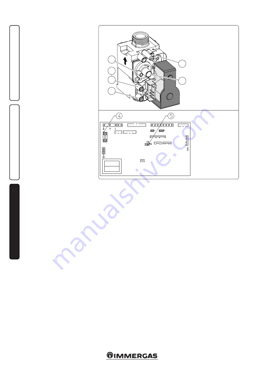
P.C.B.
Key:
1 - Gas valve inlet pressure point
2 - Gas valve outlet pressure point
3 - Off/Set adjustment screw
12 - Outlet gas flow rate regulator
Gas Valve 848
Key:
4 - Fuse 3.15 AF
5 - S34 Selector:
On = external probe;
Off = system supervisor


