RECIRCULATION KIT INSTALLATION
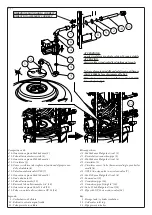
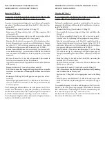
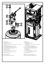
Hercules kW and Hercules condensing kW (Fig. 1).
It is recommended to lubricate the O-Ring connections with
common liquid soap slightly diluted with water.
Cut power to the appliance by disconnecting the switch upstream
from the boiler.
Remove the boiler casing.
Preparing the system
Make sure that the cold water inlet tap (12) is closed and lower
the pressure inside the storage tank / cylinder by momentarily
opening the drain valve.
Facilitate this operation by opening any hot water tap of the domestic
hot water system to let air into the storage tank.
Installation
Temporarily remove the upper insulation (1) and the cap on the
storage tank.
Connect the kit as shown in the figure.
N.B.:
pay attention to the connection of the pump whose water
circulation direction must be the same as the arrow shown in the
figure, as well as the OV20 one-way valve / non-return valve (7).
Once assembly is complete, cover the storage tank connections
with the previously removed insulation (1).
The power supply cable must be connected to a 230V ±10% / 50Hz
mains supply observing L-N polarity and earth connection; this
network must also feature an omnipolar circuit breaker of class
III overvoltage category.
Make sure to have closed the storage tank draining valve. Close the
previously opened DHW (Domestic hot water) system hot water
tap. Reopen the cold water inlet valve (12), remount the casing,
then power the boiler to bring it to normal operating conditions.
INSTALLAZIONE KIT RICIRCOLO
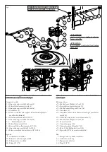
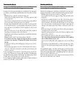
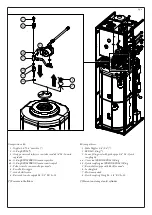
Hercules kW e Hercules condensing kW (Fig. 1).
Si suggerisce di lubrificare tutte le connessioni O-Ring tramite
comune sapone liquido diluito leggermente con acqua.
Togliere tensione all'apparecchio disalimentando l'interruttore a
monte della caldaia.
Smontare la mantellatura della caldaia.
Preparazione impianto
Accertarsi che il rubinetto ingresso acqua fredda (12) sia chiuso
e abbassare la pressione all'interno del bollitore aprendo momen-
taneamente il rubinetto di svuotamento.
Agevolare l'operazione aprendo un qualsiasi rubinetto dell’acqua calda
dell’impianto sanitario per permettere l’entrata dell’aria nel boiler.
Installazione
Asportare momentaneamente la coibentazione superiore (1) ed
eliminare il tappo presente sul bollitore.
Effettuare il collegamento del kit come rappresentato in figura.
N.B.:
prestare attenzione al collegamento della pompa che deve
avere il senso di circolazione dell'acqua uguale alla freccia rap-
presentata in figura così come la valvola unidirezionale OV20(7).
Ultimato il montaggio coprire gli allacciamenti del bollitore con
la coibentazione (1) precedentemente asportata.
Allacciare il circolatore ad una rete di 230V ±10% / 50Hz rispet-
tando la polarità L-N ed il collegamento di terra, su tale rete deve
essere prevista una disconnessione onnipolare con categoria di
sovratensione di classe III.
Accertarsi di aver chiuso il rubinetto di svuotamento boiler.
Chiudere il rubinetto dell’acqua calda dell’impianto sanitario
precedentemente aperto. Riaprire il rubinetto entrata acqua fredda
(12), rimontare la mantellatura, quindi ridare tensione alla caldaia
per portarla alle normali condizioni di funzionamento.


