background image

which is lower than the wanted signal, but which will

interfere especially in pauses between the wanted

signal. Thus, it will be possible to suppress noise,

hum, crosstalk from other channels or the undesired

sound of an instrument nearby when picking up

sound with a microphone. For compressing an audio

signal and increasing its volume subsequently, it is

most important to attenuate the noise with an

expander; otherwise it would also be amplified.

The extent of signal attenuation below the thresh-

old is adjustable via the ratio control. An expander

with an extreme expansion ratio adjusted is a gate

(= gate that will only open to allow the wanted signal

to pass through). As an effect, the final sound of an

instrument can be reduced with a gate.
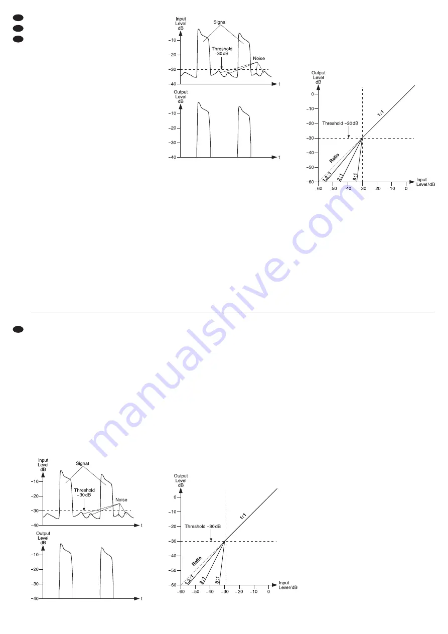
Figure 5 shows the function of a gate by means of an

input signal with a noise part and the “cleaned” out-

put signal.



Gate at a threshold of

-

30 dB

1) Set the button BYPASS/COMP (23) to COMP

(engage it). The button will light up; thus, the sig-

nal processing will be activated.

2) Adjust the threshold of the expander with the con-

trol THRESHOLD (12). First turn the control to the

left stop (position OFF). The expander will be with-

out effect and all signals will be audible. Slowly

turn the control clockwise until the expander will

only allow the wanted signal (instrument or voice)

to pass through and will suppress noise in pauses

between the wanted signal. The LEDs (4) will indi-

cate if the level of the input signal is below (-) or

above (+) the threshold adjusted.

3) Adjust the expansion ratio, i. e. the degree of

attenuation below the threshold with the control

RATIO (13). The present attenuation of the out-

put level can be read off on the LED chains GAIN

REDUCTION (8). Figure 6 shows the output level

as a function of the input level at a threshold of

-30 dB and different expansion ratios.

‘

Control characteristic of an expander

at a threshold of

-

30 dB

Note:

If the level of the noise is just below the level

of the wanted signal (e.g. for percussion micro-

phones), the gate will also be opened by the noise.

To prevent this, insert an equalizer via the

sidechain connections (

chapter 5.3). Set the

equalizer to the typical frequency range of the

wanted signal (e.g. pitch of the drum). Thus, it will

be easier to suppress noise with other frequencies.

6.3 Adjusting the compressor

6.3.1 Threshold and ratio

Adjust the threshold of the compressor with the con-

trol THRESHOLD (15) and the compression ratio

with the control RATIO (17).
Position “1”:

no compression

Position “4”:

The ratio is 4 : 1; an input level modification of

8 dB above the threshold will result in an output

level modification of 2 dB.

Position “∞”:

The compressor will operate as a signal limiter; the

output signal will roughly be limited to the value

adjusted with the control THRESHOLD (15).

The VU-meter is useful for adjusting the threshold

and the ratio. In order to be able to read off the out-

put level on the LED VU-meter (10, 11), the button

OUT/IN (21) must not be pressed. The indication

GAIN REDUCTION (8) will indicate the level reduc-

tion when the threshold is exceeded.

Figure 7 shows the output level as a function of

the input level at a threshold of -10 dB and different

compression ratios.

Figure 8 shows an input signal and the resulting

output signal at a threshold of -10 dB and a com-

pression ratio of 2 : 1. Below the threshold, the signal

will remain unchanged; above it, it will be com-

pressed by a factor of 2.

8

GB

CH

A

D

Eine Anzeige von 0 dB auf der Pegelanzeige

entspricht jeweils dem gewählten Nennpegel

-10 dBV bzw. +4 dBu.

6.2 Expander/Gate einstellen

Ein Expander verhält sich entgegengesetzt zum

Kompressor: Er vergrößert die Dynamik eines

Audiosignals. Beim Einsatz im unteren Pegelbereich

(Abwärts-Expander) werden Signale unterhalb

eines einstellbaren Pegels noch leiser. Damit lassen

sich Störsignale, die leiser als das Nutzsignal sind,

aber besonders in Nutzsignalpausen stören, gezielt

ausblenden. Rauschen, Brummen, Übersprechen

von anderen Kanälen oder der unerwünschte Klang

eines benachbarten Instruments bei einer Mikrofon-

abnahme kann so unterdrückt werden. Soll ein

Audiosignal komprimiert und anschließend in seiner

Lautstärke angehoben werden, ist es besonders

wichtig, die Störsignale mit einem Expander abzu-

schwächen, da diese sonst auch verstärkt würden.

Wie stark die Signale unterhalb der Schwelle

gedämpft werden, lässt sich mit dem Regler Ratio

einstellen. Bei einem Expander mit einem extrem

eingestellten Expansionsverhältnis spricht man von

einem Gate (= Tor, das sich nur zum Durchlassen

des Nutzsignals öffnet). Als Effekt lässt sich mit

einem Gate auch der Ausklang eines Instruments

verkürzen.
Die Abbildung 5 zeigt die Arbeitsweise eines Gates

anhand eines Eingangssignals mit einem Störsig-

nalanteil (Noise) und des „gesäuberten“ Ausgangs-

signals.



Gate bei einem Schwellwert von -30 dB

1) Die Taste BYPASS/COMP (23) auf COMP stel-

len (hineindrücken). Die Taste leuchtet und die

Signalbearbeitung ist damit eingeschaltet.

2) Mit dem Regler THRESHOLD (12) den Schwell-

wert des Expanders einstellen. Zuerst den Regler

ganz nach links drehen (Position OFF). Der

Expander ist ohne Wirkung und alle Signale sind

zu hören. Den Regler langsam so weit nach

rechts drehen, bis der Expander nur das Nutzsig-

nal (Instrument oder Stimme) unverändert durch-

lässt und in Pausen des Nutzsignals die Störge-

räusche unterdrückt. Die LEDs (4) zeigen, ob der

Pegel des Eingangssignals unterhalb (-) oder

oberhalb (+) der eingestellten Schwelle liegt.

3) Mit dem Regler RATIO (13) das Expansionsver-

hältnis, d. h. den Grad der Abschwächung unter-

halb des Schwellwertes einstellen. Die aktuelle

Dämpfung des Ausgangspegels kann an den

LED-Ketten GAIN REDUCTION (8) abgelesen

werden. Die Abbildung 6 zeigt den Ausgangspe-

gel in Abhängigkeit vom Eingangspegel bei

einem Schwellwert von -30 dB und verschiede-

nen Expansionsverhältnissen.

‘

Steuerkennlinie des Expanders bei einem

Schwellwert von

-

30 dB

Hinweis:

Liegt der Pegel der Störgeräusche nur

etwas unter dem des Nutzsignals (z. B. bei

Schlagzeugmikrofonen), wird das Gate auch

durch die Störgeräusche geöffnet. Um das zu

verhindern, kann ein Equalizer über die Side-

chain-Anschlüsse eingeschleift werden (

Kap.

5.3). Den Equalizer auf den typischen Frequenz-

bereich des Nutzsignals einstellen (z. B. Grund-

ton der Trommel). Störgeräusche mit anderen

Frequenzen lassen sich so besser unterdrücken.

Summary of Contents for 25.2170

Page 1: ... LIMITER COMPRESSEUR LIMITEUR 2 CANAUX COMPRESSORE LIMITER A 2 CANALI BEDIENUNGSANLEITUNG INSTRUCTION MANUAL MODE D EMPLOI ISTRUZIONI PER L USO VEILIGHEIDSVOORSCHRIFTEN CONSEJOS DE SEGURIDAD ŚRODKI BEZPIECZEŃSTWA SIKKERHEDSOPLYSNINGER SÄKERHETSFÖRESKRIFTER TURVALLISUUDESTA ...

Page 2: ...na 14 D A CH GB Antes de la utilización Le deseamos una buena utilización para su nuevo apa rato img Stage Line Por favor lea los consejos de seguridad detalladamente antes de hacer funcionar el aparato para protejerse y protejer la unidad de cualquier daño causado por una mala utilización guarde las instrucciones para una utilización posterior Los consejos de seguridad pueden encontrarse en la pá...

Page 3: ...3 12 13 14 15 16 17 18 19 20 21 22 23 24 25 4 5 6 7 8 9 10 11 26 27 28 29 30 31 32 33 34 28 29 30 31 32 33 34 1 2 3 ...

Page 4: ...nstead of the processed signal the sidechain control sig nal will be sent to the output 28 29 D A CH 4 GB Inhalt 1 Übersicht der Bedienelemente und Anschlüsse 4 1 1 Frontseite 4 1 2 Bedienfeld Kanal A 4 1 3 Rückseite 5 2 Hinweise für den sicheren Gebrauch 5 3 Einsatzmöglichkeiten 6 4 Aufstellmöglichkeiten 6 5 Gerät anschließen 6 5 1 Kompressor in einen Mischpult Kanal einschleifen 6 5 2 Kompressor...

Page 5: ...epaired in an expert way WARNING The unit uses dangerous mains volt age 230V Leave servicing to skilled personnel only inexpert handling may result in electric shock D A CH 5 GB 14 Taste SC MONITOR zur akustischen Kontrolle des Steuersignals ist die Taste gedrückt wird anstelle des bearbeiteten Signals das Sidechain Steuersignal auf den Ausgang 28 29 gegeben 15 Regler THRESHOLD für den Kompressor ...

Page 6: ...ntsorgung einem örtli chen Recyclingbetrieb MCL 204 INPUT MCL 204 OUTPUT Mischpult INSERT G Important for U K Customers The wires in this mains lead are coloured in accord ance with the following code green yellow earth blue neutral brown live As the colours of the wires in the mains lead of this appliance may not correspond with the coloured markings identifying the terminals in your plug proceed...

Page 7: ... werden bis eine optimale Aussteuerung erreicht ist 5 2 Inserting the compressor between two audio units The compressor can also directly be inserted between two audio units e g CD player and PA amplifier The output level of the signal source must be on line level i e when connecting a microphone for example a microphone preamplifier must be connected ahead Inputs and outputs of the com pressor ar...

Page 8: ...eeded Figure 7 shows the output level as a function of the input level at a threshold of 10 dB and different compression ratios Figure 8 shows an input signal and the resulting output signal at a threshold of 10 dB and a com pression ratio of 2 1 Below the threshold the signal will remain unchanged above it it will be com pressed by a factor of 2 8 GB CH A D Eine Anzeige von 0 dB auf der Pegelanze...

Page 9: ...n Ausgangspegel des Kompressors an den Ein gangspegel des nachfolgenden Gerätes mit dem Regler OUTPUT GAIN anpassen 6 3 3 Weicher oder harter Einsatzpunkt Ist die Taste SOFT 7 nicht gedrückt erfolgt die Kompression ab dem Schwellwert abrupt Das klingt bei großen Pegelsprüngen sehr unnatürlich Ande rerseits kann dieses aber auch ein beabsichtigter Effekt sein Damit die Kompression sanft einsetzt Co...

Page 10: ...heck the control signal acoustically press the button SC MONITOR 14 to switch it to the output Thus the compressor will operate as a de esser to attenuate sibilant sound In the same way the expander gate section can be controlled via a band pass filter matched to the corresponding instrument e g to improve channel separation when several microphones are used GB CH A D und somit unauffälliger wird ...

Page 11: ...ort beim Sprechen abgesenkt wird 5 Mit dem Regler RELEASE 20 die Zeit einstel len die verstreichen soll bis nach einer Mikro fondurchsage die Musik wieder die normale Laut stärke erreicht weiches Einblenden 6 Zur akustischen Kontrolle des Steuersignals kann dieses durch Drücken der Taste SC MONI TOR 14 auf den Ausgang geschaltet werden Ebenso kann die Expander Gate Sektion über ein Fremdsignal ges...

Page 12: ... 20 000 Hz 0 5 dB Rated level switchable 1 23 V 316 mV 4 dBu 10 dBV S N ratio 90 dB Crosstalk attenuation 100 dB THD 0 01 typ at 1 kHz and 4 dBu output level Inputs Max input level impedance connection INPUT 8 7 V 50 kΩ XLR jack 6 3 mm plug alternatively SIDECHAIN RETURN 12 3 V 10 kΩ 6 3 mm plug Outputs Max output level impedance connection OUTPUT 8 7 V 60 Ω XLR jack 6 3 mm plug SIDECHAIN SEND 8 7...

Page 13: ...13 ...

Page 14: ...s la valeur du seuil conduit à une diminution du niveau de sortie de 8 dB Indice 1 Elementi di comando e collegamenti 14 1 1 Lato frontale 14 1 2 Quadro di comando canale A 14 1 3 Lato posteriore 15 2 Avvertenze di sicurezza 15 3 Possibilità dʼimpiego 16 4 Possibilità di collocamento 16 5 Collegare lʼapparecchio 16 5 1 Inserire il compressore in un canale del mixer 16 5 2 Sistemare il compressore ...

Page 15: ...ne tension dangereuse 230 V Ne touchez jamais lʼintérieur de lʼappareil car en cas de mauvaise mani pulation vous pourriez subir une décharge électrique 14 Tasto SC MONITOR per il controllo acustico del segnale di comando se il tasto è premuto al posto del segnale elaborato allʼuscita 28 29 viene portato il segnale di comando Sidechain 15 Regolatore THRESHOLD per il compressore per impostare il pu...

Page 16: ...ment retiré du service vous devez le déposer dans une usine de recyclage adaptée pour contribuer à son élimination non polluante 1 lʼapparecchio o il cavo rete presentano dei danni visibili 2 dopo una caduta o dopo eventi simili sussiste il sospetto di un difetto 3 lʼapparecchio non funziona correttamente Per la riparazione rivolgersi sempre ad unʼofficina competente G Staccare il cavo rete afferr...

Page 17: ... le VU mètre corres pond respectivement au niveau nominal sélec tionné 10 dBV ou 4 dBu 5 2 Sistemare il compressore fra due apparecchi audio Il compressore può essere sistemato anche diretta mente fra due apparecchi audio p es lettore CD e amplificatore PA Il livello dʼuscita della sorgente di segnali deve essere Line vuol dire che collegando p es un microfono occorre inserire prima un ampli ficat...

Page 18: ... bruits pertur bateurs Pour éviter cela un égaliseur peut être inséré via les connexions Sidechain chapitre 5 3 Réglez lʼégaliseur sur la plage typique de fréquence du signal utile par exemple hauteur du son dʼun tambour De cette manière les bruits perturbateurs avec dʼautres fréquences peuvent être mieux éliminés 6 2 Impostare lʼexpander gate Un expander si comporta in modo opposto rispetto al co...

Page 19: ... inserire un equalizzatore per mezzo dei contatti sidechain Cap 5 3 Impostare lʼequalizzatore secondo le frequenze tipiche del segnale utile p es nota fondamentale del tamburo In questo modo è più facile sopprimere le interferenze con frequenze differenti 6 3 Impostare il compressore 6 3 1 Threshold e Ratio Impostare il punto dʼinserzione valore soglia del compressore con il regolatore THRESHOLD 1...

Page 20: ... de sortie devrait être généralement un peu diminué avec le réglage OUTPUT GAIN 22 ou une com pression plus importante devrait être réglée Punto dʼinserzione delicato brusco con Threshold 10 dB Ratio 10 1 6 3 4 Tempo di Attack e Release tasto AUTO I tempi di reazione in caso di superamento in alto o in basso del valore soglia possono essere regolati Se il tasto MANUAL AUTO 19 è premuto questi temp...

Page 21: ... 33 et les sorties SIDECHAIN RETURN 34 ne sont pas réglées sur le niveau 10 dBV en appuyant sur lʼinterrup teur 4 dBu 10 dBV 30 6 5 Filtro SIDECHAIN Se è premuto il tasto SC FILTER il segnale di comando per lʼelaborazione del segnale percorre un filtro passa alto Ciò riduce lʼeffetto di pompaggio che si può avere con musica con forti bassi quando per via dei toni bassi lʼintero segnale viene com p...

Page 22: ...le commutabile 1 23 V 316 mV 4 dBu 10 dBV Rapporto S R 90 dB Diafonia 100 dB Fattore di distorsione 0 01 tip con 1 kHz e livello dʼuscita 4 dBu Ingressi Livello dʼingresso max impedenza connettori INPUT 8 7 V 50 kΩ Connettore XLR Connettore jack 6 3 mm in alternativa SIDECHAIN RETURN 12 3 V 10 kΩ Connettore jack 6 3 mm Uscite Livello dʼuscita max impedenza connettori OUTPUT 8 7 V 60 Ω Connettore X...

Page 23: ...23 ...

Page 24: ...imilar 3 No funciona correctamente Sólo el personal cualificado puede reparar el apa rato bajo cualquier circunstancia G No tire nunca del cable para desconectar el en chufe de la toma de corriente tire siempre del enchufe G Utilice sólo un paño suave y seco para la limpieza no utilice nunca ni agua ni productos químicos G No podrá reclamarse garantía o responsabilidad alguna por cualquier daño pe...

Page 25: ...Enheten har andra felfunktioner Enheten skall alltid lagas av kunnig personal G Drag aldrig ur kontakten genom att dra i sladden utan ta tag i kontaktkroppen G Rengör endast med en mjuk och torr trasa an vänd aldrig kemikalier eller vatten vid rengöring G Om enheten används på annat sätt än som avses om den inte kopplas in ordentligt om den används på fel sätt eller inte repareras av auktoriserad ...

Page 26: ... Copyright by MONACOR INTERNATIONAL GmbH Co KG Bremen Germany All rights reserved A 0885 99 01 09 2008 ...

Reviews: