
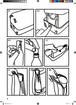


ASSEMBLY:
• Position the sparkling water system on flat and rigid surface [Fig. F]
• Remove the rear cover (7) by pressing the release key (8) [Fig. G ]
• Remove the seal (10a) and the cap (10b) present on the CO
2
cylinder (10) [Fig. H]
• Slide the CO
2
cylinder (10) through the guide (12) [Fig I]
• Tighten the CO
2
cylinder (10) to the connector (9) turning it clockwise
• Ensure that the CO
2
cylinder (10) is fully tightened
Note: never excessively tighten the cylinder to the sparkling water system as this may damage the same
system.
• Close the rear cover (7) [Fig. G]
• Before use, wash the PET bottle (5) using running water, without exceeding the temperature of 40°C.
• Fill the PET bottle (5) with cold water up to the MAX level (6b).
• Do not exceed the MAX level (6b), never drop below the MIN level (6a).
• Tilt the support for PET bottle (3) [Fig. L]
• Insert the PET bottle (5) tightening it clockwise until completely fastened [Fig. M]
• The point of the gassing tube (4) must always be immersed in the water.
USE
• Press the PUSH key (2) for about 2 seconds, slowly releasing it [Fig. N]
• To adjust the amount of CO
2
immersed in the water, repeatedly press the PUSH key (2).
• Tilt the support for PET bottle (3) [Fig. L]
• Remove the PET bottle (5), by loosening it anti-clockwise [Fig. M ].
USEFUL ADVICE
• To obtain a greater amount of bubbles use cold water, vice-versa, the warmer it is the less amount of
bubbles will be obtained.
• To maintain the flavour of the sparkling water unvaried, close the PET bottle using the cap (5a).
• The PET bottle (5) can be kept in the refrigerator.
REPLACEMENT OF THE CO
2
CYLINDER
Proceed with the replacement of the CO
2
cylinder (10) when, by pressing the PUSH key (2), the water
coming out is no longer sparkling
• Position the sparkling water system on flat and rigid surface [Fig. F]
• Remove the rear cover (7) by pressing the release key (8) [Fig. G]
• Loosen the CO
2
cylinder (10) from the connector (9) turning it anti-clockwise
• Extract the CO
2
cylinder (10) through the guide (12) [Fig I]
• Tighten the cap (10b) on the CO
2
cylinder (10) [Fig. H]
• To insert the new CO
2
cylinder, refer to the chapter ASSEMBLY
GB
7
MI000339.indd 7
08/07/10 16.41
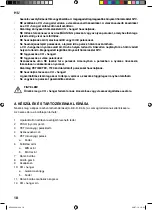
Summary of Contents for H2501
Page 3: ...IT pagina 1 EN page 5 ES página 9 RU страница 13 HU oldal 17 MI000339 indd 3 08 07 10 16 41 ...
Page 4: ...III TYPE H2501 MI000339 indd 4 08 07 10 16 41 ...
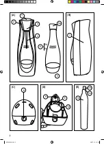
Page 5: ...I E A C D B 1 2 3 7 9 11 12 8 6 5 6a 6b 5a 10 10b 10a 4 MI000339 indd 5 08 07 10 16 41 ...
Page 6: ...II H M N I L F G MI000339 indd 6 08 07 10 16 41 ...


