


2
10782411W
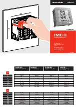
This device can be mounted just by skilled personnel.
Before mounting these meters it is necessary to verify that data on the label (measuring vol-
tage, auxiliary supply voltage, measuring current, frequency) correspond to the ones of the
network on which they are connected.
In the wiring scrupulously respect the wiring diagram; an error in connection unavoidably
leads to wrong measurements or damages to the meter.
To protect the voltmetric and auxiliary supply inputs, we suggest to insert some 0,5A fuses.
PROGRAMMING
Programming is subdivided on two levels, protected by two different numerical passwords.
LEVEL 1
Password 1000
=
customized display page, connection, current delay time and
average power, display contrast, display backlighting, pulse output.
LEVEL 2
Password 2001
=
external current and voltage transformer transformation ratios.
It is not possible to directly access to the programming level 2 but only when the pro-
gramming level 1 is over.
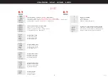
PROGRAMMABLE PARAMETERS
Password 1000
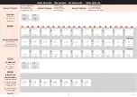
CUSTOMIZED PAGE
Possibility to load a customized display page on which you can choose which quantities the
three display lines must show.
If the user loads a customized page, this will become the standard display when the meter
switches on (as an alternative to the one showing the line voltages).
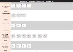
The selectable displays for the customized page are mentioned in the table 1.
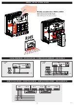
CONNECTION
The meter can be used for single-phase or three-phase network 4 wires.
The selectable connections are:
1N1E
single-phase network
3N3E
3-phase 4 wires network, 3 systems
AVERAGE POWER – AVERAGE CURRENT
Selectable delay time:
5, 8, 10, 15, 20, 30, 60 minutes
DISPLAY CONTRAST
Four values to adjust the display contrast.
DISPLAY LIGHTING
The three selectable levels (o – 50 – 100%) show the display lighting percentage in standard
conditions.(keyboard idle for more than 20 seconds).
Pressing any one of the keys, the display fully lights up (100%)
With loaded level = 100, the lighting is constant and it does not change at the pressing of
a key.
Password 2001
EXTERNAL CURRENT AND VOLTAGE TRANSFORMER TRANSFORMATION RATIO
Ct
= CT primary winding rated value (Ex. CT 800A/330mV Ct=800)
Vt
= VT primary/secondary winding ratio (EX. 600/100V Vt=6)
Ct
= selectable in the range 1…9999
Vt
= selectable in the range 1,0…12,0
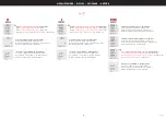
ATTENTION
For voltage direct connection (without external voltage transformer) load VT=1,0
rapporto primario/secondario TA (Ex. TA800/5A CT=160).
By modifying the CT and / or VT ratio, the KWH meters are automatically reset.
EXTERNAL CT PHASE ERROR COMPENSATION
It allows compensating the external CT phase error
Programmable
Crt
0,0…5,0° (steps 0,5°)
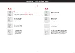
DISPLAY
Display is subdivided into four menus which are accessible by pressing the relevant function keys:
U / I / P-Q-S / E-T
U
voltage
I
current
P-Q-S
power
E-T
energy, power factor, frequency, run hour meter
Once entered a menu, by pressing many times the same key you can display all the pages
related to the chosen quantity.
In the first three display lines, beside the numeric values, there are some bar indicators which
show the measured values as percentage of the nominal value. In the fourth display line
there is always the energy counting.
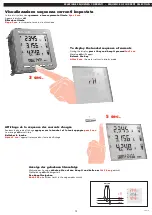
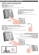
PHASE SEQUENCE CHECK
It allows to verify the correct voltage terminal connection
(2-5-8-11)
To display the “interlinked voltages” page
Simultaneously press keys
123 YES
display = correct sequence
Err 123
display = wrong sequence
Press to return to the standard display
SEQUENCE OF CURRENT SELECTION
The meter is programmed for sequence of currents
rH
= I1 – I2 – I3 (right-hand)
It is possible to select the sequence of currents
LH
= I3 – I2 – I1 (left-hand)
You can access the selection during the display phase without entering the program-
ming menu
L’installazione di questo apparecchio deve essere effettuata esclusivamente da personale
qualificato.Prima di procedere alla installazione, verificare che i dati di targa (tensione di
misura, tensione di alimentazione ausiliaria, corrente di misura, frequenza) corrispondano a
quelli effettivi della rete a cui viene collegato lo strumento.
Nei cablaggi rispettare scrupolosamente lo schema di inserzione, una inesattezza nei collega-
menti è inevitabilmente causa di misure falsate o di danni allo strumento.
A protezione degli ingressi voltmetrici e di alimentazione ausiliaria è consigliabile inserire dei
fusibili 0,5A.
PROGRAMMAZIONE
La programmazione è suddivisa su due livelli, protettI da due differenti password numeriche
LIVELLO 1
Password 1000
=
pagina visualizzazione personalizzata, connessione, tempo integrazione
corrente e potenza media, contrasto display, retroilluminazione display, uscita impulsi.
LIVELLO 2
Password 2001
=
rapporto trasformazione TA e TV esterni.
Non è possibile accedere direttamente al livello 2 di programmazione, ma solo al termine
della programmazione livello 1.
PARAMETRI PROGRAMMABILI
Password 1000
PAGINA VISUALIZZAZIONE PERSONALIZZATA
Possibilità di impostare una pagina di visualizzazione personalizzata, in cui scegliere quali
grandezze far comparire nelle tre righe di visualizzazione.
Se l’utente imposta una pagina personalizzata, questa diventerà la visualizzazione standard
all’accensione dello strumento (in alternativa a quella riportante le tensioni di linea).
Le visualizzazioni selezionabili per la pagina personalizzata sono riportate nella tabella 1.
CONNESSIONE
Lo strumento può essere utilizzato per linea monofase o trifase 4 fili.
Le inserzioni selezionabili sono:
1N1E
linea monofase
3N3E
linea trifase 4 fili, 3 sistemi
POTENZA MEDIA - CORRENTE MEDIA
Tempo integrazione selezionabile:
5, 8, 10, 15, 20, 30, 60 minuti
CONTRASTO DISPLAY
Quattro valori regolazione contrasto display
ILLUMINAZIONE DISPLAY
I tre livelli selezionabili (0 - 50 - 100%) indicano la percentuale di illuminazione display in
condizioni normali (inattività della tastiera per un tempo superiore ai 20 secondi).
Premendo uno qualsiasi dei tasti, il display si illumina completamente (100%)
Con livello impostato = 100% l’illuminazione è costante e non cambia alla pressione di un
tasto.
Password 2001
RAPPORTO TRASFORMAZIONE TRASFORMATORI ESTERNI
Ct
= valore nominale primario TA (Es. TA800A/330mV Ct =800)
Vt
= rapporto primario/secondario TV (Es. TV600/100V Vt =6)
Ct
= selezionabile nel campo 1...9999
Vt
= selezionabile nel campo 1,0...12,0
ATTENZIONE
Per inserzione diretta in tensione (senza TV esterno) impostare Vt=1,0.
Modificando il rapporto trasformazione TA e/o TV i contatori di energia vengono azzerati
automaticamente.
COMPENSAZIONE ERRORE DI FASE TA ESTERNI
Consente di compensare l’errore di fase dei TA esterni
Crt
programmabile 0,0...5,0° (passi 0,5°)
VISUALIZZAZIONE
La visualizzazione è suddivisa in quattro menù, accessibili premendo i relativi tasti funzione:
U / I / P-Q-S / E-T
U
tensione
I
corrente
P-Q-S
potenza
E-T
energia, fattore di potenza, frequenza, contaore
Entrati in un menù, premendo più volte lo stesso tasto si visualizzano tutte le pagine relative
alla grandezza scelta.
Nelle prime tre righe di visualizzazione, a fianco dei valori numerici, sono presenti degli indi-
catori a barra che esprimono i valori misurati in percentuale del valore nominale.
Nella quarta riga di visualizzazione è sempre presente il conteggio di energia.
CONTROLLO SEQUENZA FASI
Permette di verificare l’esatto collegamento dei morsetti tensione
(2-5-8-11)
Visualizzare la pagina “tensioni concatenate”.
Premere contemporaneamente i tasti
Visualizzazione
123 YES
= sequenza corretta
Visualizzazione
Err 123
= sequenza errata
Premere per tornare alla normale visualizzazione
SELEZIONE SEQUENZA CORRENTI
Lo strumento è programmato per sequenza correnti
rH
= I1 – I2 – I3 (right-hand)
E’ possibile selezionare la sequenza correnti
LH
= I3 – I2 – I1 (left-hand)
La selezione è accessibile in fase di visualizzazione senza entrare nel menù di programmazione.
ISTRUZIONI PER L’INSTALLAZIONE
MOUNTING INSTRUCTIONS