


14 |
P a g e
WasteStation Compact
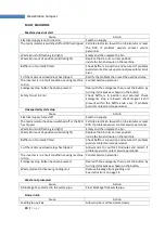
NORMAL OPERATION
1.
Ensure that safety baffle is closed and the interlock knob is screwed down fully but lightly.
(Do not overtighten).
2.
Press green button to start. This activates the start-up sequence. Allow 20 seconds to fully
complete the start up.
3.
Feed waste into the hopper at a slow uniform rate (not too fast), using the feeding pusher if
necessary, briefly allowing each load to clear the macerator before feeding in the next batch.
4.
If the macerator stalls or is severely overloaded, it may cause the automatic cut out on the
motor to operate. Once the motor has cooled it can be re-started. Note that stopping the
motor and restarting it reverses the direction of the rotor and can help to relieve an
overload. If the machine remains stalled, see RELEASING A JAM below.
5.
If overly wet food goes into the waste bin then the rate of feeding the hopper should be
decreased, and the unit allowed to run with no food for a short while to allow it to flush.
RELEASING A JAM
Food Waste Disposers can jam under overload or if unsuitable materials are placed inside.
IMC machines are designed to withstand this and no damage will normally result, as the
machine will switch itself off. It is necessary to clear the jam as follows:
1.
Switch off at the mains isolating switch.
2.
Remove the baffle by unscrewing the interlock knob and lifting off.
3.
Take out any bulk waste in the disposal chamber. Rubber gloves are recommended
4.
If the item, which blocked the disposer, is apparent, remove it.
5.
A release wrench is provided with which to turn the rotor if it is jammed. Place the
hexagon socket of the wrench over the hexagonal boss on the centre of the rotor,
or the tines into the rotor and against the cutting edges (depending on the type of
key supplied) lever backwards and forwards until the jammed material releases.
Remove the release wrench and remove the material.
6.
Replace the wrench, and ensure that the rotor is totally free throughout its full
rotation.
7.
Remove the release wrench
8.
Replace the baffle, screwing the interlock knob fully home.
9.
Switch on at the mains isolating switch.
10.
Press the START button and continue disposal.
In the event of difficulty, call your supplier or the manufacturer for a qualified service
engineer.
Summary of Contents for WasteStation Compact
Page 3: ...3 P a g e WasteStation Compact MACHINE DIMENSIONS ...
Page 4: ...4 P a g e WasteStation Compact View on Rear of Machine Showing Connections for Services ...
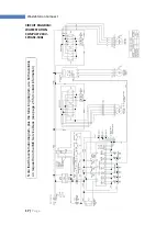
Page 13: ...13 P a g e WasteStation Compact ...
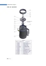
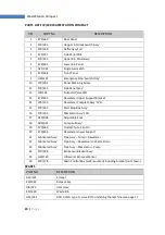
Page 18: ...18 P a g e WasteStation Compact PARTS LIST MACERATOR ...
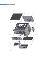
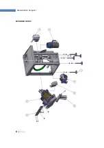
Page 19: ...19 P a g e WasteStation Compact EXPLODED VIEW 1 ...
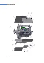
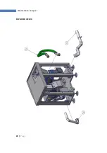
Page 20: ...20 P a g e WasteStation Compact EXPLODED VIEW 2 ...
Page 21: ...21 P a g e WasteStation Compact EXPLODED VIEW 3 ...
Page 22: ...22 P a g e WasteStation Compact EXPLODED VIEW 4 ...