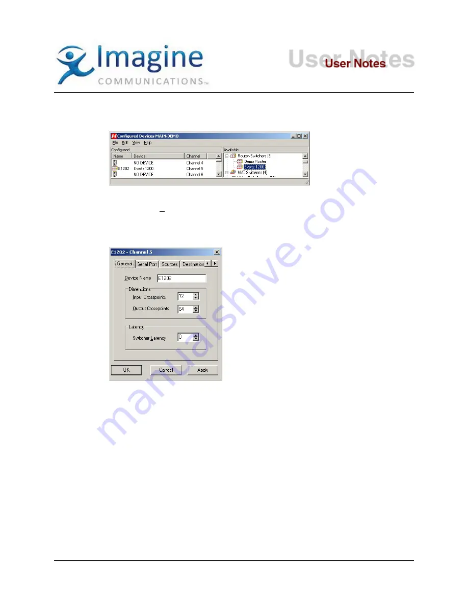
2. From the list in the right hand pane select “
E
VERTZ
1200
” from the
“Router/Switchers
”
category. Use the mouse pointer to drag this item over the top of one of the icons in the
right hand pane that has the caption “NO DEVICE”.
3. Select the
E1202
icon you just created and press the right mouse button to bring up a
menu. Select “Properties” from this menu, or simply double-click on the icon instead.
4. Select the
General
tab to set the other parameters. Each of these parameters is
explained below (always remember to click
Apply
if you have changed something on the
tab:
•
Device Name:
An identifier up to 16 characters that is displayed in the device status
window and is used as the ID when secondary switcher crosspoint events are used.
•
Input Crosspoints
: Number of sources on the router. This should normally be left at
the default setting of 12.
•
Output Crosspoints
: There can only be two destinations on the 1200 series, but this
should be set to the base a 1 (see Device Setup notes). The router will
ignore crosspoints that are lower than the base address, or higher than the base
a1.
•
Latency
: The value is in frames (-999 to 999) and can be used to adjust the switcher
for frame accuracy. The default setting of 0 should normally be used.
5.
Serial Port
: Select the Serial Port tab. Set this to the physical serial port number on the
Device Server where the router is connected (start from the first serial card on the left;
the ports are numbered top-down). You need not use the same value as the Channel
number for the Serial Port, although it may make troubleshooting easier for you in the
future.
•
Sources
: Select the Sources tab and fill in descriptions (up to 8 characters) and
crosspoints for each of the source inputs. This is important if you plan on using the
© 2015 Imagine Communications Corp.
Proprietary and Confidential
13-May-2015| Page 4 of 7


