11
Normal
Operation
Section 3
DISPLAY FUNCTIONS
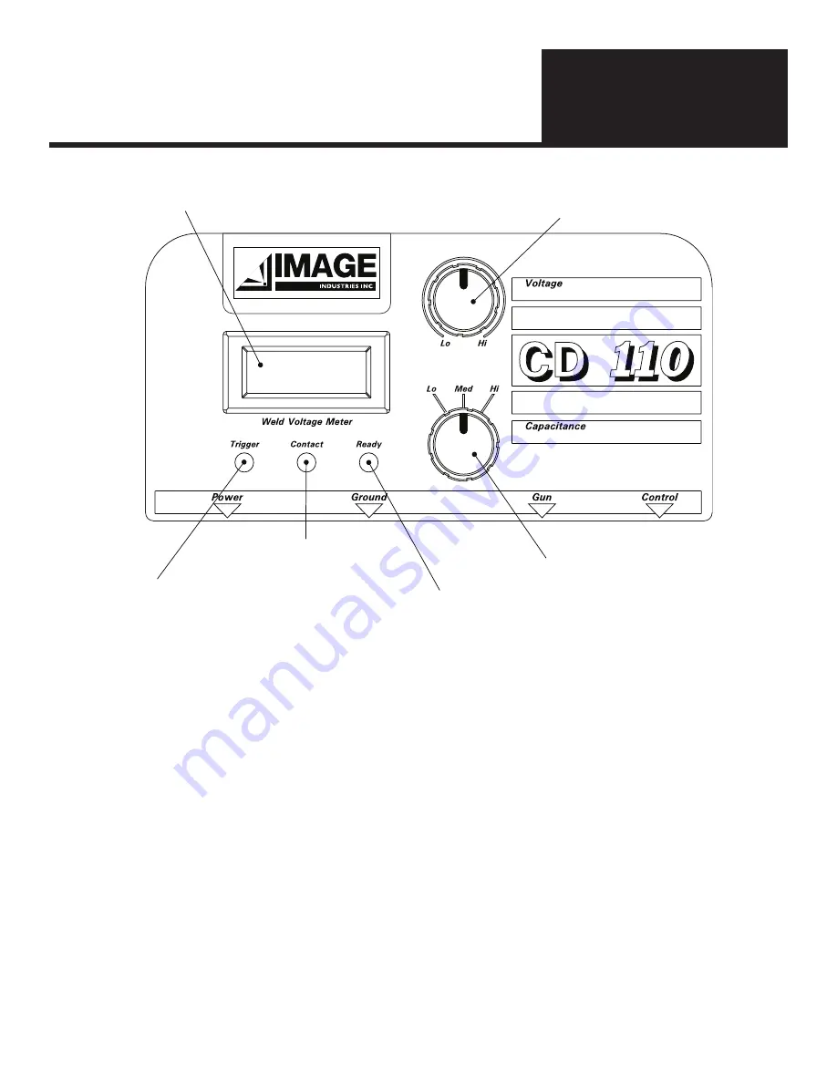
The main Weld Voltage Display shows the voltage that will be used for welding.
There are 3 indicator lights.
Trigger (Red)
This indicator lights when the trigger is pulled. This shows there is a good connection through
the gun trigger switch and cables.
Contact (Amber) This indicator lights when the unit detects contact with the work. This means there is a good
welding path.
Ready (Green)
This indicator lights when the unit is ready to weld. If the operator changes the weld voltage,
this light will go out for a moment as the proper voltage is reached. This light can also flash out
error codes if certain error conditions occur (see troubleshooting for specific error conditions).
ROTARY KNOBS
Voltage Control Knob
The upper rotary knob controls the weld voltage. Turning the knob clockwise increases the weld voltage up to about
190V, turning the knob counter clockwise will decrease the weld voltage down to about 40V. The power supply will take a
moment to achieve the desired setting. Small changes make it easier to hit a target voltage level.
Capacitance Select Knob
The lower rotary knob has 3 positions. The operator can select from 3 different capacitance levels.
Low: 66,000uF
Medium: 88,000uF
High: 110,000uF
These different capacitance levels allow the power supply to be fine tuned to match the exact welding application for the
highest quality, most repeatable results
.
Voltage Display
Voltage
Adjustment Knob
Capacitance
Adjustment Knob
(Green) Lights when welder
is ready to weld
(Red) Lights when gun
trigger is pulled
(Amber) Lights when
there is a good weld path


