Ilumen
8
Installation Manual Ilumen PIDbox Light v1.2
6
E
LECTRICAL CONNECTIONS
When installing the Ilumen PIDbox Light, the AC side of the PV plant must be switched off. Also
the DC switch of the inverter must be switched off. After the installation is done, you can switch
the DC switch back on followed by the AC side of the PV plant.
A standard AC outlet must be available on installation. This outlet should be on at all times. The
ideal solution is to have a single outlet with a single circuit breaker of 16A.
6.1
E
ARTH CONNECTION
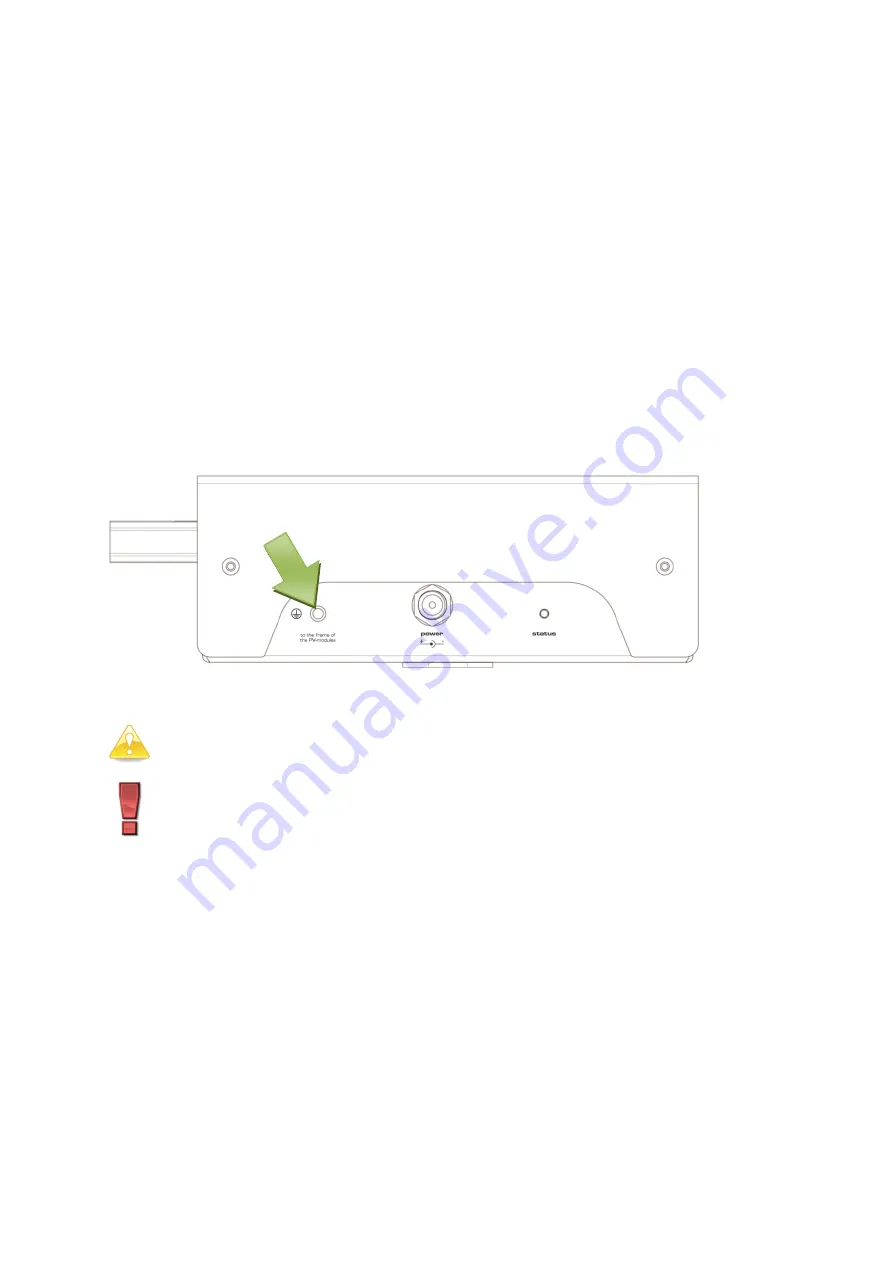
To achieve the best result, the frames of the solar modules must be connected to the earth
connector of the Ilumen PIDbox Light. For optimal result you must lay a cable (2.5-4mm
2
) to the
mounting structure of the solar modules (make sure mounting structures and frames of the solar
modules are electrically conducting). It is important that all frames of all solar modules are at
the earth potential, if necessary you have to interconnect the mounting structures with
additional cables.
6.2
S
OLAR ARRAY AND INVERTER
(MPPT)
CONNECTIONS
When installing the PIDbox Light between the PV array and inverter always
switch off the DC switch of the inverter and/or in the DC combiner boxes.
When doing any kind of work on the PIDbox Light, always disconnect the
DC power plug from the device before unplugging any PV-cables.
Always connect the PIDbox Light in parallel with the PV arrays. On the Ilumen PIDbox Light the
“A
PV
in +” plug should be connected to
the positive side of the strings of the 1
st
MPPT and
the “A
PV in
–“ plug should be connected to
the negative side of the strings of the 1
st
MPPT. The strings
of a 2
nd
MPPT should be connected in the same
manner to the “B
PV
in” plugs.
You can use free
inputs on the inverter to make these parallel connections. If there are none available, you must
use a splitter cable to properly connect the PIDbox light
All unused inputs and outputs have to be terminated with a corresponding sealing plug.


