background image

ENGLISH

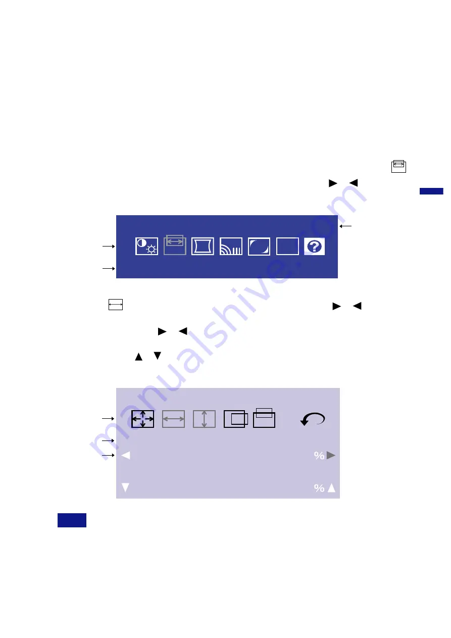
H-Size

Screen Control

50

Adjustment icon

Adjustment menu

presently selected

The line shows the
p r o g r e s s   o f   t h e
adjustment being
made.

| | | | | | | | | | | | | | | | | | | | | | | | |

· · · · · · · · · · · · · · · · · · · · · · · · ·

V-Size

50

| | | | | | | | | | | | | | | | | | | | | | | | |

· · · · · · · · · · · · · · · · · · · · · · · · ·

OPERATING THE MONITOR

To create the best picture, your iiyama Vision Master has been preset at the factory with the signal

timings listed on page 19 in

 PRESET MODES. If an incorrect picture appears during the operation,

adjust  the  image  by  following  the  procedure  shown  below  to  get  the  desired  picture.

After selecting an item in the Main Menu, the adjustments and settings
are made in the Sub-Menu.

For  example,  to  adjust  the  horizontal  screen  size,  select 
(Screen Control) on the Main Menu by using the 

 / 

 Buttons.

The Sub-Menu appears when you press the Menu Button.

B

The  On  Screen  Display  disappears  in  optional  setting  seconds  after  you  stop  pressing  the
buttons while performing an adjustment. (See page 13 for OSD Off Timer.)

n

n

NOTE

Select 

 (H-Size) on the Sub-Menu by using the   / 

 Buttons.

An  adjustment  scale  will  turn  white  when  you  press  the  Menu
Button. Use the 

 / 

 Buttons to adjust the horizontal screen size.

The vertical screen size adjustment can be also made on this screen
by using the   /    Buttons. See ADJUSTMENT MENU CONTENTS on
next pages for further information.

C

(

Adjustments  for  Size,  Position,  Pin-Cushion  and  Trapezoid  are  saved  for  each  signal  timing.
Except for these adjustments, all other adjustments such as Color, Parallelogram, Convergence,
Moire, and Landing have only one setting which applies to all signal timings.

Main  Menu  appears  on  the  screen  when  you  press  the  Menu
Button.

Screen Control

Menu

IN 1 

RB

FUNC

Adjustment icon

Adjustment menu

presently selected

Signal input connector
presently selected

OPERATING THE MONITOR      8

All manuals and user guides at all-guides.com

all-guides.com

Summary of Contents for Vision Master Pro 514 HM204DT A

Page 1: ...tor Please keep this manual in a safe place for your future reference CUSTOMER SERVICE CLEANING BEFORE YOU OPERATE THE MONITOR FEATURES LOCATION OF CONTROLS OPERATING THE MONITOR ADJUSTMENT MENU CONTE...

Page 2: ...tain time beneficial both for the user and the environment Electrical safety Emissions Electromagnetic fields Noise emissions Ecology The product must be prepared for recycling and the manufacturer mu...

Page 3: ...ion this may be determined by monitoring the interference while turning the equipment off and on you are encouraged to try to correct the interference by one of the following measures n Reorient or re...

Page 4: ...ck OPERATE UNDER THE SPECIFIED POWER SUPPLY Be sure to operate the monitor only with the specified power supply Use of an incorrect voltage will cause malfunction and may cause fire or electric shock...

Page 5: ...if they are placed on or near the monitor as the degauss circuit causes a strong momentary magnetic field WHEN YOU INSTALL THE MONITOR ON YOUR COMPUTER Be sure the computer is strong enough to hold t...

Page 6: ...cessor or display text and a like then your eyes maybe subject to fatigue This will be because the right side of characters will appear stretched bright and slightly out of focus This is normal becaus...

Page 7: ...ent solvent For safety reasons turn off the power switch and unplug the monitor before you clean it n If you drop any materials or liquids such as water into the monitor when cleaning unplug the power...

Page 8: ...ls However with older operating systems and or BIOS settings in your computer the USB hub may not operate In this case please contact your computer dealer first for advice n Power Cable n Signal Cable...

Page 9: ...ts is connected to the signal source the one connected is automatically selected Input Select Button is not available if there is no signal input from the selected connector or during the power manage...

Page 10: ...les used for the connection vary by the type of computers you use An incorrect connection may cause serious damage to both the monitor and the computer The cable supplied with the monitor is for a sta...

Page 11: ...ter you stop pressing the buttons while performing an adjustment See page 13 for OSD Off Timer n n NOTE Select H Size on the Sub Menu by using the Buttons An adjustment scale will turn white when you...

Page 12: ...performing the direct adjustment irrespective of OSD Off Timer setting See page 13 for OSD Off Timer n ADJUSTMENT MENU CONTENTS Direct Too soft Too loud Direct Volume Control NOTE Only available on Di...

Page 13: ...r Temp is selected n sRGB is an international standard which defines and unifies the difference of color appearance between equipment n You can not adjust the Contrast Brightness Red Blue OPQ and Gamm...

Page 14: ...low Too high Return to Menu Screen Control Too small Too large Main Menu Problem Option Button to Press Tilt To correct tilt Return to Menu Pin Cushion Trapezoid Pin Balance Return to Main Menu To cor...

Page 15: ...ing or swiveling the monitor In this case first select Degauss If the problem persists perform the Landing adjustments NOTE Degauss should not be repeated continuously Wait at least 30 minutes between...

Page 16: ...ss OSD H Position OSD V Position Function Deutsch Fran ais Nederlands Svenska Language English English German French Dutch Swedish Japanese Lockout All adjustment items except this function are locked...

Page 17: ...turn to Main Menu NOTE Performing this operation resets any adjustment data made by the user to the factory preset frequencies The following settings made by the user for signals other than the factor...

Page 18: ...t complies with every power saving requirement of ENERGY STAR and VESA DPMS When activated it automatically reduces unnecessary power consumption of the monitor when your computer is not in use To use...

Page 19: ...persists If you are experiencing a problem which is not described below or you cannot correct the problem discontinue using the monitor and contact your dealer or iiyama service center for further ass...

Page 20: ...until the problem disappears Damper Wires The two faint horizontal lines that may be visible on the screen are actually the shadows of steel wires called Damper Wires All Diamondtron U3 CRT based mon...

Page 21: ...mmended Resolution 1600 1200 at 100Hz Separate sync TTL Positive or Negative Composite sync 1 TTL Positive or Negative Sync on green 1 0 3Vp p Negative Factory presets 9 User defined settings 9 maximu...

Page 22: ...ings vary depending on the type of graphics board you use NOTE Pin Ground 19 APPENDIX Positive Positive Positive Negative Negative 1280 1024 85Hz 1024 768 800 600 85Hz 640 480 85Hz 640 480 60Hz 85 0Hz...

Page 23: ...nual is printed on recycled paper Dieses Handbuch ist auf Recyclingpapier gedruckt Ce manuel est imprim sur du papier recycl Deze handleiding is op kringlooppapier gedrukt Handboken har tryckts p retu...

Reviews: