background image

DXXi KVM Extender 

32 

2011-06-01 

3.7 

Status LEDs 

Pos: 25 /806-IHSE/Beschreibung/Diagnose LEDs/472-xx @ 6\mod_1304494283852_6.doc @ 50434 @  


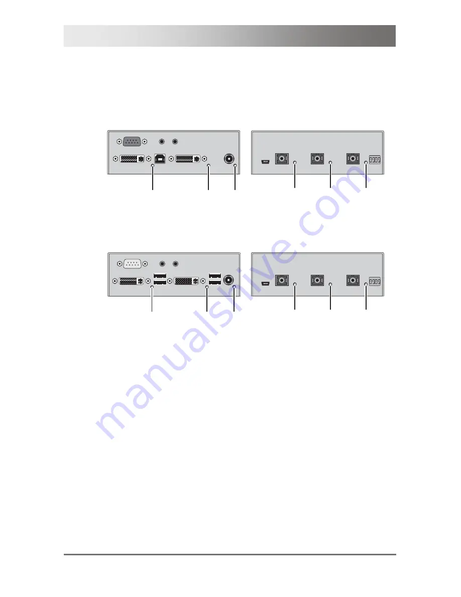
The KVM Extender is fitted with the following LEDs for status indication at 
CPU Unit and CON Unit: 


CPU Unit 

CPU Unit 

1

2

3


4

5

6


Rear View 

Front View 


CON Unit 

CON Unit 

1

2

3


4

5

6


Rear View 

Front View 


Summary of Contents for K472 Series

Page 1: ...IHSE GmbH Maybachstrasse 11 88094 Oberteuringen Germany info ihse de www ihse de Tel 49 7546 9248 0 Fax 49 7546 9248 48 User Manual Edition 2011 06 01 DXXi KVM Extender Model K472 Series...

Page 2: ...al the manufacturer assumes no liability for errors or omissions Neither does the manufacturer assume any liability for damages resulting from the use of the information contained herein The manufactu...

Page 3: ...de Kits 11 3 5 Accessories 11 3 6 Device Views 12 3 6 1 Model K472 SSH 12 3 6 2 Model K472 SWH 13 3 6 3 Model K472 SSHA 14 3 6 4 Model K472 SST 16 3 6 5 Model K472 SSTA 17 3 6 6 Model K472 SDH 19 3 6...

Page 4: ...Function option 40 7 Specifications 41 7 1 Interfaces 41 7 1 1 DVI D Single Link 41 7 1 2 DVI D Dual Link 41 7 1 3 USB HID 41 7 1 4 USB 2 0 transparent 42 7 1 5 Fiber Type SC Interconnect 42 7 1 6 Ser...

Page 5: ...l Support 55 9 1 Support Checklist 55 9 2 Shipping Checklist 55 10 Regulatory and Standards Compliance 56 10 1 CE Declaration Of Conformity 56 10 2 North American Regulatory Compliance 57 10 3 WEEE 57...

Page 6: ...de is printed on the base of the devices 1 3 Cautions and Notes The following symbols are used in this manual This symbol indicates an important operating instruction that should be followed to avoid...

Page 7: ...replacements Do not use a power supply if it appears to be defective or has a damaged case Connect all power supplies to grounded outlets In each case ensure that the ground connection is maintained...

Page 8: ...109 2 3 1 Application The KVM Extender is used to increase the distance between a source computer CPU and its console keyboard mouse and other peripheral devices The KVM Extender is designed for use w...

Page 9: ...CPU Unit and the CON Unit communicate with each other through the interconnect cables 1 2 4 5 7 6 3 System overview 1 Source computer CPU 2 KVM Extender CPU Unit 3 Interconnect cable 4 KVM Extender CO...

Page 10: ...Head KVM Extender for 1x DVI Dual Link up to 2560x2048 2x USB HID keyboard mouse and analog audio serial option K472 SDT Single Head KVM Extender for 1x DVI Dual Link up to 2560x2048 4x USB 2 0 K472...

Page 11: ...plate to mount by screws 286 2K Mounting plate to mount by snap on Pos 8 806 IHSE Beschreibung Zubeh r 472 xx 6 mod_1304503895633_6 doc 50759 2 3 5 Accessories Model Description 260 5U International p...

Page 12: ...U USB HID 3 Connect to 5VDC power supply 1 Service port 2 Connect to interconnect cable Link C 3 Configuration DIP switches CON Unit 1 2 3 1 2 3 Rear View Front View 1 Connect to DVI monitor 2 Connect...

Page 13: ...y 1 Service port 2 Connect to interconnect cable Link C 3 Configuration DIP switches CON Unit 1 2 3 1 2 3 Rear View Front View 1 Connect to DVI monitor 2 Connect to USB HID devices 3 Connect to 5VDC p...

Page 14: ...SSHA CPU Unit 5 6 1 2 3 4 1 2 3 Rear View Front View 1 To CPU DVI D 2 To CPU USB HID 3 Connect to 5VDC power supply 4 Connect to serial D Sub 9 5 Audio IN 6 Audio OUT 1 Service port 2 Connect to inter...

Page 15: ...or 2 Connect to USB HID devices 3 Connect to 5VDC power supply 4 Connect to serial D Sub 9 5 Audio IN 6 Audio OUT 1 Service port 2 Connect to interconnect cable Link C 3 Configuration DIP switches Pos...

Page 16: ...nnect cable Link C 4 Configuration DIP switches CON Unit 1 2 3 4 1 2 3 4 Rear View Front View 1 Connect to DVI monitor 2 Connect to USB 2 0 devices 1 3 Connect to USB 2 0 devices 2 4 Connect to 5VDC p...

Page 17: ...4 1 2 3 4 Rear View Front View 1 To CPU DVI D 2 To CPU USB 2 0 3 Connect to 5VDC power supply 4 Connect to serial D Sub 9 5 Audio IN 6 Audio OUT 1 Service port 2 Connect to interconnect cable Link A 3...

Page 18: ...1 3 Connect to USB 2 0 devices 2 4 Connect to 5VDC power supply 5 Connect to serial D Sub 9 6 Audio IN 7 Audio OUT 1 Service port 2 Connect to interconnect cable Link A 3 Connect to interconnect cabl...

Page 19: ...nect to interconnect cable Link C 4 Configuration DIP switches CON Unit 1 2 3 1 2 3 4 Rear View Front View 1 Connect to DVI monitor 2 Connect to USB HID devices 3 Connect to 5VDC power supply 1 Servic...

Page 20: ...3 4 1 2 3 4 Rear View Front View 1 To CPU DVI D 2 To CPU USB HID 3 Connect to 5VDC power supply 4 Connect to serial D Sub 9 5 Audio IN 6 Audio OUT 1 Service port 2 Connect to interconnect cable Link...

Page 21: ...B HID devices 3 Connect to 5VDC power supply 4 Connect to serial D Sub 9 5 Audio IN 6 Audio OUT 1 Service port 2 Connect to interconnect cable Link B 3 Connect to interconnect cable Link C 4 Configura...

Page 22: ...t to interconnect cable Link B 4 Connect to interconnect cable Link C 5 Configuration DIP switches CON Unit 1 2 3 4 1 2 3 4 5 Rear View Front View 1 Connect to DVI monitor 2 Connect to USB 2 0 devices...

Page 23: ...K472 SDTA CPU Unit 5 6 1 2 3 4 1 2 3 4 5 Rear View Front View 1 To CPU DVI D 2 To CPU USB 2 0 3 Connect to 5VDC power supply 4 Connect to serial D Sub 9 5 Audio IN 6 Audio OUT 1 Service port 2 Connec...

Page 24: ...B 2 0 devices 2 4 Connect to 5VDC power supply 5 Connect to serial D Sub 9 6 Audio IN 7 Audio OUT 1 Service port 2 Connect to interconnect cable Link A 3 Connect to interconnect cable Link B 4 Connect...

Page 25: ...nect cable Link B 3 Connect to interconnect cable Link C 4 Configuration DIP switches CON Unit 1 2 3 1 2 3 4 Rear View Front View 1 Connect to DVI monitor 2 Connect to USB HID devices 3 Connect to 5VD...

Page 26: ...ct to interconnect cable Link C 4 Configuration DIP switches CON Unit 1 2 3 4 1 2 3 4 Rear View Front View 1 Connect to DVI monitor 1 2 Connect to USB HID devices 3 Connect to DVI monitor 2 4 Connect...

Page 27: ...4 Rear View Front View 1 To CPU DVI D 1 2 To CPU USB HID 3 To CPU DVI D 2 4 Connect to 5VDC power supply 5 Connect to serial D Sub 9 6 Audio IN 7 Audio OUT 1 Service port 2 Connect to interconnect cab...

Page 28: ...ices 3 Connect to DVI monitor 2 4 Connect to 5VDC power supply 5 Connect to serial D Sub 9 6 Audio IN 7 Audio OUT 1 Service port 2 Connect to interconnect cable Link B 3 Connect to interconnect cable...

Page 29: ...erconnect cable Link B 4 Connect to interconnect cable Link C 5 Configuration DIP switches CON Unit 5 1 2 3 4 1 2 3 4 5 Rear View Front View 1 Connect to DVI monitor 1 2 Connect to USB 2 0 devices 1 3...

Page 30: ...STA CPU Unit 5 6 7 1 2 3 4 1 2 3 4 5 Rear View Front View 1 To CPU DVI D 1 2 To CPU USB 2 0 3 To CPU DVI D 2 4 Connect to 5VDC power supply 5 Connect to serial D Sub 9 6 Audio IN 7 Audio OUT 1 Service...

Page 31: ...Connect to USB 2 0 devices 2 5 Connect to 5VDC power supply 6 Connect to serial D Sub 9 7 Audio IN 8 Audio OUT 1 Service port 2 Connect to interconnect cable Link A 3 Connect to interconnect cable Li...

Page 32: ...eschreibung Diagnose LEDs 472 xx 6 mod_1304494283852_6 doc 50434 The KVM Extender is fitted with the following LEDs for status indication at CPU Unit and CON Unit CPU Unit CPU Unit 1 2 3 4 5 6 Rear Vi...

Page 33: ...ed Flashing Monitor DDC is being transmitted from the console monitor 2 Video OK 2 red optional On DVI signal from video source available Off Device not ready 3 Power red On Device ready Off No connec...

Page 34: ...tup DVI video cable 1 8 m DVI D male to male USB cable 1 8 m type A to type B Additional content for Dual Head devices DVI video cable 1 8 m DVI D male to male Additional content for devices with inte...

Page 35: ...CON Unit Installation 2 Connect your monitor s keyboard and mouse to the CON Unit 3 Connect the CON Unit with the interconnect cable s 4 Connect the 5VDC power supply to the CON Unit CPU Unit Install...

Page 36: ...s This section illustrates typical installations of KVM Extenders Pos 19 806 IHSE Installation Installationsbeispiele VAR_KVM_Single Dual Head_USB 2 0 5 mod_1278575500636_258 doc 41826 1 2 4 5 3 KVM E...

Page 37: ...USB 2 0 1 Source computer CPU 2 KVM Extender CPU Unit 3 Interconnect cable 4 KVM Extender CON Unit 5 Console monitor keyboard mouse 6 Second monitor option only with Dual Head devices 7 USB 2 0 devic...

Page 38: ...e depending from the respective device DIP settings have to be performed both CPU and CON unit into the same positions Only set DIP switches if the extender is not connected to power supply DIP Functi...

Page 39: ...cted keyboard commands are available The following table lists the keyboard commands to enter and to exit Command Mode and to change the Hot Key sequence Function Keyboard Command Ctrl Left Shift i Ho...

Page 40: ...ill now be able to read the actual monitor DDC information and so allow the required video resolution to be selected Pos 36 806 IHSE Betrieb Switchbetrieb 472 xx 6 mod_1304495129258_6 doc 50561 2 6 2...

Page 41: ...Link 6 mod_1306496783354_6 doc 51660 3 7 1 2 DVI D Dual Link The video interface supports the DVI D protocol All signals that comply to DVI D Dual Link norm can be transmitted This includes e g monito...

Page 42: ...s without restriction USB 2 0 data transfer is supported with USB high speed max 480 Mbit s Each USB 2 0 port provides a maximum current of 500 mA high power Pos 43 806 IHSE Technische Daten Schnittst...

Page 43: ...ignal A serial mouse and a single 2 wire transmission In this case choose X ON X OFF software handshake for traffic control at printer and PC Connection Format DTE Data Terminal Equipment Speed Up to...

Page 44: ...ted with the microphone input of the sound card red Adjust the sound card to provide an additional amplification 20 dB The output of the CPU Unit is connected to the audio input of the sound card blue...

Page 45: ...house patch cable I AD ZN H 4G50 in house or outdoor breakout cable resistant Multi Mode 62 5 m One fiber 62 5 m I V ZN HH 2G62 5 in house breakout cable A DQ ZN B2Y 4G62 5 outdoor cable with protect...

Page 46: ...s that are not supported as standard will normally operate with our devices featuring transparent USB support Please note that concurrent operation of more than two USB HID devices is not possible eve...

Page 47: ...data 0 2 T M D S data 2 10 T M D S data 1 18 T M D S data 0 3 T M D S data 2 GND 11 T M D S data 1 GND 19 T M D S data 0 GND 4 n c 12 n c 20 n c 5 n c 13 n c 21 n c 6 DDC Input SCL 14 5VDC high impeda...

Page 48: ...13 T M D S data 3 21 T M D S data 5 6 DDC Input SCL 14 5VDC high impedance 22 T M D S clock GND 7 DDC Output SDA 15 GND 23 T M D S clock 8 Internal use 16 Hot Plug recognition 24 T M D S clock C1 Int...

Page 49: ...2 Data White 3 Data Green 4 n c 5 1 5 GND Black Pos 57 806 IHSE Technische Daten Pinbelegungen Glasfaser Typ SC 6 mod_1304499047977_6 doc 50615 Fiber Type SC Picture Diode Signal 1 Data IN OUT Pos 58...

Page 50: ...max 800 mA Dual Head devices max 950 mA USB 2 0 devices max 1 500 mA CPU max 3 500 mA CON Pos 62 806 IHSE Technische Daten Einsatzbedingungen ATB_Einsatzbedingungen 5 mod_1278578980026_6 doc 42480 2...

Page 51: ...ecifications 2011 06 01 51 7 8 Shipping Weight CPU Unit CON Unit 0 8 kg 1 7 lb Shipping Box 3 4 kg 7 5 lb Pos 65 806 IHSE Hilfe im Problemfall UEB_Hilfe im Problemfall 5 mod_1278579113839_6 doc 42536...

Page 52: ...computer CPU Check DVI D cable to CPU Download DDC information from console monitors see Chapter 6 1 Page 40 Reboot CPU if necessary No monitor detected Check connection length and quality of the DVI...

Page 53: ...8 806 IHSE Hilfe im Problemfall St rung am USB HID Anschluss 472 xx 6 mod_1304499779915_6 doc 50723 2 8 3 USB HID Diagnosis Possible Reason Measure Keyboard LEDs Shift and Scroll are flashing Keyboard...

Page 54: ...CPU Unit Check interconnect cable and connectors USB device without function USB 2 0 device is not supported Check installation at the CPU also the necessary drivers New connection of the USB 2 0 devi...

Page 55: ...e existing manual Nature circumstances and duration of the problem Involved components such as graphic source CPU OS graphic card monitor USB HID USB 2 0 devices interconnect cable including manufactu...

Page 56: ...uipment EN 55022 2006 A1 2007 Class A EN 55024 1998 A1 2001 A2 2003 This declaration certifies the conformity to the specified directives but contains no assurance of properties The safety instruction...

Page 57: ...he party responsible for compliance could void the user s authority to operate the equipment Shielded cables must be used with this equipment to maintain compliance with radio frequency energy emissio...

Page 58: ...d it is part of the PAL TV standard CON Unit Component of a KVM Extender or Media Extender to connect to the console monitor s keyboard and mouse optionally also with USB 2 0 devices CPU Unit Componen...

Page 59: ...een Display is used to display information or to operate a device Quad Head A system with four video connections RCA Cinch A not standardized plug connection for transmission of electrical audio and v...

Page 60: ...ata input There is no need for a special driver during installation New USB HID device found is reported Typical HID devices include keyboards mice graphics tablets and touch screens Storage video and...

Reviews: