background image

Draco vario IP CPU KVM KVM Extender 

16 

2018-07-12 


Pos: 16 /806-IHSE/Beschreibung/Geräteansichten/474-xx/6-fach Vario-Gehäuse 474-BODY6R @ 6\mod_1304580442488_6.doc @ 50894 @ 3 @ 1 


3.6.4 

6-fold Vario Chassis 474-BODY6R 

CPU and CON Unit 


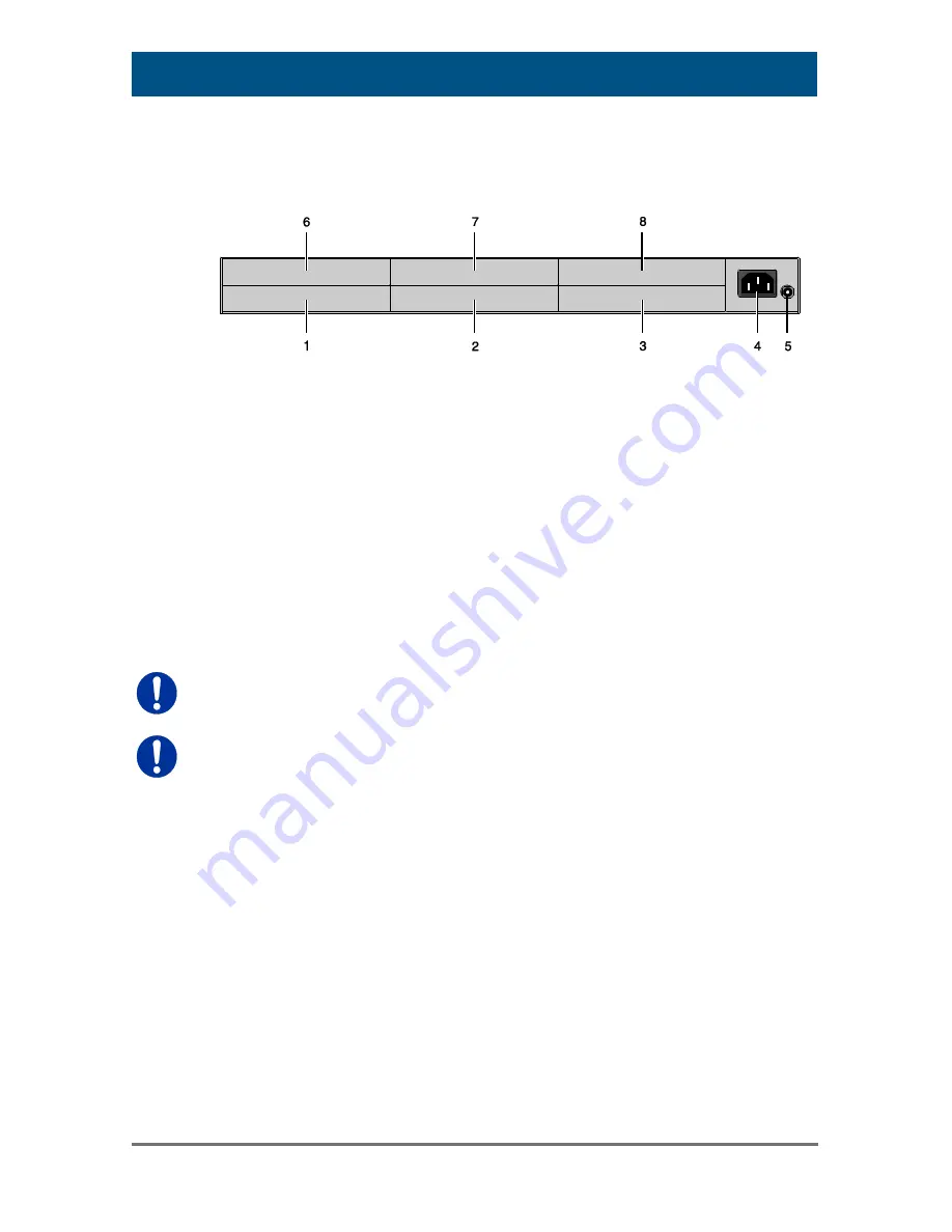
Rear View 

Slot for modules #5 

Slot for modules #3 

Slot for modules #1 

Connect to power supply (standard) 

Connect to 5VDC power supply (standard) 

Slot for modules #6 

Slot for modules #4 

Slot for modules #2 


For operation with KVM Extender modules in a 6-fold vario chassis, two 
power supplies are necessary. In this case, redundancy is inapplicable. 


The 6-fold vario chassis is not equipped with a fuse on its primary side. 
Therefore the protection against excessive currents has to be provided by 
the electrical installation of the building. 


Pos: 17 /806-IHSE/zz_Layout/Seitenumbruch @ 8\mod_1348581820516_0.doc @ 69462 @  @ 1 


Summary of Contents for Draco vario IP CPU

Page 1: ...IHSE GmbH Maybachstraße 11 88094 Oberteuringen Germany info ihse com www ihse com phone 49 7546 9248 0 fax 49 7546 9248 48 Draco vario IP CPU 488 Series KVM Extender User Manual Edition 2018 07 12 ...

Page 2: ...ion of this manual the manufacturer assumes no liability for errors or omissions The manufacturer assumes no liability for damages resulting from the use of the information contained herein The manufacturer reserves the right to change specifications functions or circuitry of the product without notice The manufacturer cannot accept liability for damage due to misuse of the product or due to any o...

Page 3: ... Kits 12 3 5 Accessories 13 3 6 Device Views 14 3 6 1 2 fold Vario Chassis 474 BODY2 2R 14 3 6 2 2 fold Vario Chassis 474 BODY2N 14 3 6 3 4 fold Vario Chassis 474 BODY4 4R 15 3 6 4 6 fold Vario Chassis 474 BODY6R 16 3 6 5 6 fold Vario Chassis 474 BODY6BP 17 3 6 6 6 fold Vario Chassis 474 BODY6BPF 18 3 6 7 21 fold Vario Chassis 474 BODY21R 19 3 6 8 Model L488 BIPEC BIPECR 20 3 6 9 Model L488 BIPES ...

Page 4: ...U Units 32 5 6 Remote Access Configuration 34 6 Operation 38 6 1 Download of DDC Information 38 6 2 Shared Operation of redundant CPU Units 38 7 Specifications 40 7 1 Interfaces 40 7 1 1 Single Link 40 7 1 2 USB HID 40 7 1 3 USB 2 0 transparent 41 7 1 4 RJ45 Interconnect 41 7 1 5 Fiber SFP Type LC Interconnect 41 7 1 6 RJ45 Network 42 7 2 Interconnect Cable 43 7 2 1 Cat X 43 7 2 2 Fiber 44 7 3 Sup...

Page 5: ...3 8 4 USB 2 0 embedded 54 8 5 Compute Module 55 9 Technical Support 56 9 1 Support Checklist 56 9 2 Shipping Checklist 56 10 Certificates 57 10 1 CE Declaration Of Conformity 57 10 2 North American Regulatory Compliance 58 10 3 Product Safety 59 10 4 WEEE 59 10 5 RoHS RoHS 2 59 11 Glossary 60 Pos 1 806 IHSE Zu diesem Handbuch ATB_Zu diesem Handbuch 5 mod_1278573163276_6 doc 41510 1222 1 ...

Page 6: ...and Notes The following symbols are used in this manual This symbol indicates an important operating instruction that should be followed to avoid any potential damage to hardware or property loss of data or personal injury This symbol indicates important information to help you make the best use of this product This symbol indicates best practice information to show recommended and optimal ways to...

Page 7: ...t or manufacturer approved replacements Do not use a power supply if it appears to be defective or has a damaged chassis 7 Connect all power supplies to grounded outlets In each case ensure that the ground connection is maintained from the outlet socket through to the power supply s AC power input 8 Do not connect the link interface to any other equipment particularly network or telecommunications...

Page 8: ...th Cat X Twisted Pair interconnect cables or fiber interconnect cables The KVM Extender with Cat X interconnect cables is unsuitable for connection between buildings where a fiber optic based product should be used instead The KVM Extender with fiber interconnect cables can also be used with applications in environments which are subject to electromagnetic interference Electromagnetic interference...

Page 9: ...PU via TCP IP network cable The CON module is connected to the console monitor keyboard and mouse The CPU Unit and the CON modules communicate with each other through the interconnect cables System Overview 1 Source computer CPU 2 TCP IP network cable 3 KVM Extender IP CPU Unit 4 Interconnect cable 5 KVM Matrix 6 KVM Extender CON Unit 7 Console monitor keyboard mouse See Chapter 4 3 Page 27 for in...

Page 10: ...tible with devices in the K47x and K48x series 3 3 2 Chassis Model Description 474 BODY2 Empty chassis for up to 2 boards 1x external power supply unit 474 BODY2R Empty chassis for up to 2 boards 1x external power supply unit preparation for redundancy for a second power supply unit external 474 BODY2N Empty chassis for up to 2 boards 1x internal power supply unit preparation for redundancy for a ...

Page 11: ...M Extender Modules Model Description L488 BIPEx Single Head IP CPU extender module for 1x Single Link up to 1920x1200 2x USB HID and 2x USB 2 0 embedded L488 BIPExR Single Head IP CPU extender module for 1x HDMI Single Link up to 1920x1200 with 2x USB HID USB 2 0 embedded and redundant connector for interconnect cables Pos 7 806 IHSE Beschreibung Überwachungsmodule 474 xx 14 mod_1415202166328_6 do...

Page 12: ...y for 2 and 4 fold chassis 474 PSU2 Power supply for 2 fold chassis spare or redundancy 474 PSU4 Power supply for 4 fold chassis spare or redundancy 474 PSU6 Power supply for 6 fold chassis spare or redundancy 474 PSU21 Power supply for 6 fold chassis spare or redundancy 474 BLND1 Blind plate 3U 4HP for 2 4 and 6 fold chassis 474 BLND2 Blind plate 3U 8HP for 2 4 and 6 fold chassis 474 6FAN Fan opt...

Page 13: ... cable 1 8 m VGA to DVI I 436 HD HDMI cable 1 8 m DVI D 436 DVHD Adapter DVI D male to HDMI female 445 2H DVI D splitter cable 455 CK Stereo jack cable 1 6 m 3 5 mm Stereo 455 CR RCA cable 2 5 m Cinch male connector 455 CT TOSLINK cable 1 8 m F05 male connector 455 CX Mini XLR cable 1 8 m 3 pole 474 IECLOCK IEC connection cable for power supply lockable Pos 10 806 IHSE Beschreibung Geräteansichten...

Page 14: ...12 806 IHSE Beschreibung Geräteansichten 474 xx 2 fach Vario Gehäuse 474 BODY2N 8 mod_1348578478411_6 doc 69380 3 1 3 6 2 2 fold Vario Chassis 474 BODY2N CPU and CON Unit Rear View 1 Slot for modules 1 2 Connect to power supply standard 3 Slot for modules 2 4 Connect to 5VDC power supply redundancy The 2 fold vario chassis with an internal power supply is not equipped with a fuse on its primary si...

Page 15: ...lot for modules 3 2 Slot for modules 1 3 Connect to 5VDC power supply standard 4 Slot for modules 4 5 Slot for modules 2 6 Connect to 5VDC power supply redundancy optional For operation with three KVM Extender CON modules and a USB 2 0 CON module in a 4 fold vario chassis two power supplies are necessary In this case redundancy is inapplicable Pos 15 806 IHSE zz_Layout Seitenumbruch 8 mod_13485818...

Page 16: ...pply standard 5 Connect to 5VDC power supply standard 6 Slot for modules 6 7 Slot for modules 4 8 Slot for modules 2 For operation with KVM Extender modules in a 6 fold vario chassis two power supplies are necessary In this case redundancy is inapplicable The 6 fold vario chassis is not equipped with a fuse on its primary side Therefore the protection against excessive currents has to be provided ...

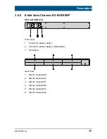
Page 17: ...74 BODY6BP CPU and CON Unit Front View 1 Connect to power supply 1 2 Connect to power supply 2 redundancy 3 Grounding Rear View 1 Slot for modules 5 2 Slot for modules 3 3 Slot for modules 1 4 Slot for modules 6 5 Slot for modules 4 6 Slot for modules 2 Pos 19 806 IHSE Beschreibung Geräteansichten 474 xx 6 fach Vario Gehäuse 474 BODY6BPF 11 mod_1392644763729_6 doc 132650 3 1 ...

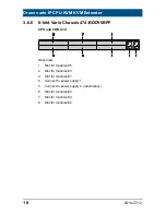
Page 18: ...w 1 Slot for modules 5 2 Slot for modules 3 3 Slot for modules 1 4 Connect to power supply 1 5 Connect to power supply 2 redundancy 6 Slot for modules 6 7 Slot for modules 4 8 Slot for modules 2 Pos 20 806 IHSE Beschreibung Geräteansichten 474 xx 21 fach Vario Gehäuse 474 BODY21R 8 mod_1348579151346_6 doc 69400 3 1 ...

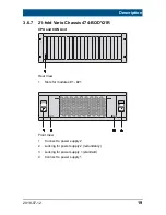
Page 19: ...ront View 1 Connect to power supply 2 2 Locking for power supply 2 redundancy 3 Locking for power supply 1 standard 4 Connect to power supply 1 Pos 21 806 IHSE zz_Layout Seitenumbruch 8 mod_1348581820516_0 doc 69462 1 Pos 22 806 IHSE Beschreibung Geräteansichten 481 xx Typ L R481 BHHC 9 mod_1367828248520_6 doc 71714 3 4 ...

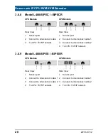
Page 20: ...1 xx Typ L R481 BHHCR 9 mod_1373967661662_6 doc 77531 3 4 3 6 9 Model L488 BIPES BIPESR CPU Module CPU Module Rear View Rear View 1 Service port 2 Connect to interconnect cable 1 3 Connect to interconnect cable 2 4 To CPU TCP IP network 1 Service port 2 Connect to interconnect cable 1 3 Connect to interconnect cable 2 4 To CPU TCP IP network Pos 24 806 IHSE Beschreibung Geräteansichten 481 xx Typ ...

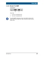
Page 21: ...ect to network RJ45 The 474 SNMP module can be only used with the chassis 474 BODY6BP F and 474 BODY21 with a production date later than March 2014 IHSE zz_Layout Seitenumbruch 8 mod_1348581820516_0 doc 69462 1 Pos 56 806 IHSE Beschreibung Diagnose LEDs UEB_Diagnose_LEDs 6 mod_1304584004723_6 doc 51146 2 1 ...

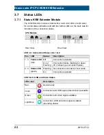
Page 22: ...the connection status CPU Module Rear View Rear View LED 1 4 Connection Status Link 1 2 Pos LED Status Description 1 3 Failure LED red Off Connection available On or Flashing Connection failure flashing for about 20 s following a connection failure 2 4 Status LED green Flashing No connection via interconnect cable On Connection available LED 5 6 USB and Video Status LED color Description Red Devic...

Page 23: ...8 USB 2 0 embedded Status LED color Description Green Active USB 2 0 embedded link to CON Unit Light Blue green flashing USB 2 0 host detected Light blue flashing USB 2 0 host and devices detected LED 9 10 Connection Status TCP IP network Pos LED Status Description 9 Traffic LED green Off No network traffic Flashing Network traffic available 10 Link LED green Off or flashing No network connection ...

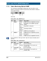
Page 24: ...ashing Registration in progress Green flashing Operating condition Green SNMP board de registered 4 Status 2 White SNMP board is in registration process Status Description White SNMP board is in registration process Due to variations in LED type white might also appear as light purple or light blue Status LEDs of the network port Pos LED Status Description 2 Link status orange Off Port not activat...

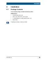
Page 25: ... 1 Package Contents Your extender package contains the following items KVM Extender KVM Extender CPU Unit Draco vario chassis incl power supply 1x redundancy 2x country specific power cord Quick Setup If anything is missing contact your dealer Pos 67 806 IHSE Installation System anschließen 474 xx 6 mod_1304584542160_6 doc 51273 233 1 ...

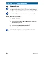
Page 26: ...ng of the devices comply with the requirements see Chapter 7 Page 40 4 2 1 KVM Extender Setup 1 Switch off all devices CPU Unit Installation 2 Connect the TCP IP network cable to the CPU Unit Please ensure the cables are not strained 3 Connect the CPU Unit to the interconnect cable s 4 Connect the 5VDC power supply to the CPU Unit 5 Power up the system To power up the system the following sequence...

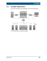
Page 27: ...27 4 3 Example Applications This section illustrates a typical installation of IP CPU KVM extenders IP CPU KVM extender installation example Pos 70 806 IHSE Installation Betriebsmodi 481 xx 9 mod_1373975439223_6 doc 77658 2 4 ...

Page 28: ... most cases Downloading of the DDC information of the console monitor can be performed during normal operation see Chapter 6 1 Page 38 For special requirements DDC information can be retrieved and uploaded as a binary file to both the CPU Unit and the CON Unit Connect your computer with a USB mini cable to the service port of the CPU Unit or CON Unit The data area of the unit is now accessible as ...

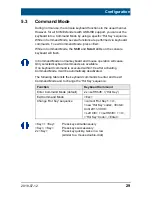
Page 29: ...rd will flash In Command Mode normal keyboard and mouse operation will cease Only selected keyboard commands are available If no keyboard command is executed within 10 s after activating Command Mode it will be automatically deactivated The following table lists the keyboard commands to enter and to exit Command Mode and to change the Hot Key sequence Function Keyboard Command Enter Command Mode d...

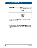
Page 30: ... Left Alt 6 2x Right Shift 7 2x Right Ctrl 8 2x Right Alt Set freely selectable Hot Key exemplary In order to set a freely selectable Hot Key e g 2x Space use the following keyboard sequence current Hot Key c 0 Space Enter Reset Hot Key In order to set a Hot Key back to default settings of the extender press the key combination Right Shift Del within 5 s after plugging in a keyboard Pos 76 806 IHS...

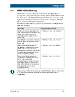
Page 31: ... Unit Hot Key h w Enter Activates the emulation of already stored device descriptions in the CPU Unit Hot Key h e Enter Deactivates the emulation of active device descriptions in the CPU Unit The input devices connected to the CON Unit will be now passed transparently to the source computer CPU Hot Key h d Enter Deactivates the emulation of active device descriptions in the CPU Unit Deletes the de...

Page 32: ...st line of the Config txt file 5 5 1 Parameters for CPU Units You can write the following parameters into the configuration file of a CPU Unit DDC Management Parameter Function ENAHPDET Enable hotplug switch for K238 5x series LOCKEDID Activate DDC write protection Digital Audio Parameter Function SRC32000 Activate sample rate conversion sample rate 32 kHz only with digital audio upgrade module SR...

Page 33: ...te high compression rate ENADITHER Activate dithering filter for Mac OS systems Shared Operation Parameter Function RELEASETIME n Release timer n 0 9 seconds for Mouse and Keyboard Connect without parameter 2 seconds General Settings Parameter Function DISPLAY2 Show video channel 2 per default after switching on the respective Dual Head unit 482 series only ...

Page 34: ...signment of the IP Session to the IP CPU Device The minimum firmware requirement for the Draco tera KVM matrix is version V03 06 and version 3 6 0 0 for the Java tool Tera tool You have the following option to perform the configuration In order to configure the IP CPU extender proceed as follows IP Session Configuration The configuration of the IP session includes the relevant settings for the rem...

Page 35: ...resolution of the remote connection default 1920x1080 10 If the remote connection should be performed in Full Screen check the corresponding check box 11 If you want to transmit digital HDMI audio check the box Sound 12 Press the button Apply to confirm your configuration settings Any IP session config can be assigned to multiple IP CPU Devices at the same time IP CPU EXT Unit Configuration The co...

Page 36: ...t Mask Gateway NTP server TimeZone and Keyboard Layout Direct IP Session Assignment This type of configuration allows the exclusive access of one IP session only In order to assign a single IP session to an IP CPU Device proceed as follows 1 Select Definition CPU Devices in the main menu of the Java tool and open the tab CPU 2 Select the IP CPU Device to be configured in the list of Devices 3 Sele...

Page 37: ...r to assign multiple IP session configs to an IP CPU Device proceed as follows 1 Select Definition CPU Devices in the main menu of the Java tool and open the tab CPU 2 Press the Button Configure IP CPU on the bottom of the working area A pop up window will appear Menu Configure IP CPU 3 Follow the instructions of the configuration wizard and perform the assignment accordingly 4 After finishing the...

Page 38: ...will go black for a short time At the same time Command Mode is closed and the keyboard LEDs return to previous status 3 Restart the corresponding source computer CPU The video mode has been readjusted Screen quality should be optimal The CPU should now show the console monitor as the current screen together with the available video resolutions The DDC information of the console monitor was loaded...

Page 39: ...e n defines the time in seconds and has to be replaced by the numbers 0 to 9 e g RELEASETIME 5 If this parameter is not activated at all the release time is set to 2 seconds by default The parameter RELEASETIME X deactivates the shared operation 4 Save your changes 5 Reboot the CPU Unit Example View Config txt When using redundant CPU Units in combination with a KVM matrix the function of competin...

Page 40: ...e Code Modulation LPCM DTS DTS HD 5 1 Dolby Digital Dolby Digital Plus 5 1 Bit Depth 16 to 24 bit Sample Rate 32 to 192 kHz Pos 85 806 IHSE Technische Daten Schnittstellen USB HID 5 mod_1278578292214_6 doc 42150 3 1 7 1 2 USB HID Our devices with USB HID interface support a maximum of two devices with USB HID protocol Each USB HID port provides a maximum current of 100 mA Keyboard Compatible with ...

Page 41: ...f 500 mA high power When using a USB high speed interface with 4 USB ports respectively 2 connectors provides a maximum of 500 mA high power and 2 connectors a maximum of 100 mA Pos 88 806 IHSE Technische Daten Schnittstellen RJ45 Gerätekommunikation 5 mod_1278578339308_6 doc 42186 3 1 7 1 4 RJ45 Interconnect Communication between Cat X devices requires a 1000BASE T connection Connector wiring mus...

Page 42: ...g to EIA TIA 568 B 100BASE T with RJ45 connectors at both ends All four wire pairs are used in both directions The cabling is suitable for a full duplex operation For the cable connection to a source computer CPU a crossed network cable cross cable must be used Pos 92 806 IHSE Technische Daten Schnittstellen Serielle Schnittstelle RS422 9 mod_1362475591209_6 doc 71309 3 1 ...

Page 43: ...Extender requires interconnect cabling specified for Gigabit Ethernet 1000BASE T The use of solid core AWG24 shielded Cat 5e or better is recommended Cat X Solid Core Cable AWG24 S UTP Cat 5e cable according to EIA TIA 568 B Four pairs of wires AWG24 Connection according to EIA TIA 568 B 1000BASE T Cat X Patch Cable AWG26 8 S UTP Cat 5e cable according to EIA TIA 568 B Four pairs of wires AWG26 8 ...

Page 44: ...s 50μm I V ZN H 2G50 in house patch cable I AD ZN H 4G50 in house or outdoor breakout cable resistant Multi mode 62 5μm Two fibers 62 5μm I V ZN HH 2G62 5 in house breakout cable A DQ ZN B2Y 4G62 5 outdoor cable with protection against rodents Maximum Acceptable Cable Length Type of cable Maximum Acceptable Cable Length Single mode 9μm 10 000 m 32 800 ft Single mode 9μm XV 5 000 m 16 400 ft Multi ...

Page 45: ...firmware may be required USB HID and other devices that are not supported as standard will normally operate with our devices featuring transparent USB support Please note that concurrent operation of more than two USB HID devices is not possible even if you use a USB hub Pos 102 806 IHSE Technische Daten Unterstützte Peripherie USB 2 0 Geräte 5 mod_1278578553933_6 doc 42278 3 1 7 3 2 USB 2 0 Devic...

Page 46: ...a graphical interface RemoteFX Enhanced remote desktop protocol Microsoft to handle graphics intensive applications Virtual Network Computing VNC Platform independent graphical desktop sharing system to remotely control a source computer CPU Secure Shell SSH Cryptographic network protocol for operating network services securely over an unsecured network in a client server architecture Pos 103 806 ...

Page 47: ...hnische Daten Pinbelegungen RJ45 5 mod_1278578820011_6 doc 42405 1 RJ45 interconnect Picture Pin Signal Pin Signal 1 D1 5 D3 2 D1 6 D2 3 D2 7 D4 4 D3 8 D4 Pos 110 806 IHSE Technische Daten Pinbelegungen Glasfaser SFP Typ LC 5 mod Fiber SFP Typ LC Picture Diode Signal 1 Data OUT 2 Data IN RJ45 TCP IP network Picture Pin Signal Pin Signal 1 D1 5 n c 2 D1 6 D2 3 D2 7 n c 4 n c 8 n c ...

Page 48: ...0 240 V 47 63 Hz 474 BODY6BP 1 300 mA max 100 240 V 50 60 Hz 474 BODY6BPF 1 300 mA max 100 240 V 50 60 Hz 474 BODY21 4U 4 000 mA max 2x 100 240 V 50 60 Hz DC Power Supply Model Max Current Max Voltage 474 BODY2 2R 3 000 mA 5 VDC 474 BODY2N 5 000 mA 5 VDC 474 BODY4 4R 5 000 mA 5 VDC 474 BODY6R 8 000 mA 5 VDC Power Requirement Power Requirement per Unit KVM Extender Non redundant devices max 1 400 m...

Page 49: ...gurator on the website Pos 122 806 IHSE Technische Daten Abmessungen 474 xx 6 mod_1304586358176_6 doc 51345 2 1 7 8 Size Devices in the 2 fold Vario Chassis 1 CPU Unit CON Unit 145 x 147 x 41 mm 5 7 x 5 8 x 1 7 Shipping Box 210 x 140 x 165 mm 8 3 x 5 5 x 6 5 Devices in the 2 fold Vario Chassis 2 CPU Unit CON Unit 221 x 147 x 41 mm 8 7 x 5 8 x 1 7 Shipping Box 550 x 365 x 115 mm 21 7 x 14 4 x 4 5 D...

Page 50: ... 7 9 Shipping Weight Devices in the 2 fold Vario Chassis 1 CPU Unit CON Unit 0 7 kg 1 5 lb Shipping Box 2 5 kg 5 5 lb Devices in the 2 fold Vario Chassis 2 CPU Unit CON Unit 1 1 kg 2 4 lb Shipping Box 2 9 kg 6 4 lb Devices in the 4 fold Vario Chassis CPU Unit CON Unit 0 9 kg 2 0 lb Shipping Box 3 4 kg 7 5 lb Devices in the 6 fold Vario Chassis 6R CPU Unit CON Unit 1 9 kg 4 2 lb Shipping Box 5 1 kg...

Page 51: ...ig txt parameter without function Parameter not set or saved Write parameter into Config txt file and save changes Start Command CFG not set Write start command CFG into first line of the Config txt file Parameter written incorrectly Check correct spelling and capitalization Extender not restarted Restart extender Pos 127 806 IHSE Hilfe im Problemfall Bildausfall 481 xx 9 mod_1367842260491_6 doc 7...

Page 52: ...urce computer CPU Check DVI D cable to CPU Download DDC information from console monitors see Chapter 6 1 Page 38 Reboot CPU if necessary CON Unit LED 3 violet No monitor detected Check connection length and quality of the DVI D cable to monitor tighten cable thumbscrews No video signal detected from CPU Unit Check connection length and quality of interconnect cables between the units Download DDC...

Page 53: ...ction of USB cable to USB HID device Remove DVI and power cable and restart CON Unit Connect power cable first USB device without function No USB HID device Connect USB HID device USB HID device is not supported Contact dealer if necessary Pos 129 806 IHSE Hilfe im Problemfall Störung am seriellen Anschluss 474 xx 6 mod_1304586713332_6 doc 51418 2 1 Pos 130 806 IHSE Hilfe im Problemfall Störung am...

Page 54: ...er USB port if necessary Remove USB and power cable and restart CPU Connect power cable first CPU Unit LED 2 4 off No connection between CON Unit and CPU Unit Check interconnect cable and connectors CPU Unit LED 8 flashing green No USB 2 0 device Connect USB 2 0 device USB 2 0 device is not supported Check installation at the CPU also the necessary drivers New connection of the USB 2 0 device Cont...

Page 55: ... Kernel not active Check TCP IP network cable to CPU Unit Repower IP CPU Unit CPU Unit LED 7 violet Application not active Check application on compute module Repower IP CPU Unit CPU Unit LED 10 flashing or off TCP IP network connection failure Check connected network devices e g network switch Check TCP IP network cable connection ...

Page 56: ...te of the existing manual Nature circumstances and duration of the problem Components included in the system such as graphic source CPU OS graphic card monitor USB HID USB 2 0 devices interconnect cable including manufacturer and model number Results from any testing you have done 9 2 Shipping Checklist 1 To return your device contact your dealer to obtain a RMA number Return Material Authorizatio...

Page 57: ...lectromagnetic compatibility 2014 35 EU Council Directive on the harmonization of the laws of the Member States relating to the making available on the market of electrical equipment designed for use within certain voltage limits CE Marking Product list 488 Series The products comply with the following harmonized standards for Information Technology Equipment EN 55032 2012 EN 55024 2010 A1 2015 EN...

Page 58: ...ul interference when the equipment is operated in a commercial environment This equipment generates uses and can radiate radio frequency energy and if not installed and used in accordance with the instruction manual may cause harmful interference to radio communications Operation of this equipment in a residential area is likely to cause harmful interference in which case the user will be required...

Page 59: ...te ATB_WEEE 5 mod_1278579673292_6 doc 42704 2 1 10 4 WEEE The manufacturer complies with the EU Directive 2012 19 EU on the prevention of waste electrical and electronic equipment WEEE The device labels carry a respective marking Pos 142 806 IHSE Zertifikate ATB_RoHS 5 mod_1278579714214_6 doc 42722 2 1 10 5 RoHS RoHS 2 This device complies with the Directive 2011 65 EU of the European Parliament a...

Page 60: ... it is part of the PAL TV standard CON Unit Component of a KVM Extender or Media Extender to connect to the console monitor s keyboard and mouse optionally also with USB 2 0 devices Console Keyboard mouse and monitor CPU Unit Component of a KVM Extender or Media Extender to connect to a source computer CPU CVBS The analog color video baseband signal CVBS is also called Composite Video and it is pa...

Page 61: ...face for an all digital transmission of audio and video data It is differentiated between the HDMI standards 1 0 to 1 4a The signals have TMDS level KVM Keyboard video and mouse Mini XLR Industrial standard for electrical plug connections 3 pole for the transmission of digital audio and control signals Multi mode 62 5µ multi mode fiber cable or 50µ multi mode fiber cable OSD The On Screen Display ...

Page 62: ...n CVBS TOSLINK Standardized fiber connection system for digital transmission of audio signals F05 plug connection Triple Head A system with three video connections USB HID USB HID devices Human Interface Device allow for data input There is no need for a special driver during installation New USB HID device found is reported Typical HID devices include keyboards mice graphics tablets and touch scr...

Reviews: