NOTE: DIAGRAMS AND ILLUSTRATIONS NOT TO SCALE
WARNING
Hot glass will cause burns.
Do not touch glass until cooled.
Never allow children to touch glass.
•
Install only when fireplace is OFF and COLD.
•
Fireplace surfaces get EXTREMELY HOT!
•
The glass on the front of the fireplace reaches
EXTREMELY HIGH temperatures and can cause severe
burns if touched. Even after the gas is turned off, fireplace
surfaces remain extremely hot.
•
Keep children away from an operating fireplace. Closely
supervise children in any room where a fireplace is
operating to prevent contact with glass.
GENERAL INFORMATION
These blower kits may be used with the INNOVATIVE HEARTH
PRODUCTS fireplace models listed herein. The blower is
installed beneath the firebox. Room air is drawn in through
the bottom area of the fireplace, heated as it passes across the
firebox, and discharged through the upper panel/louver area at
the top of the fireplace.
FBK-100 Blower Kit
Use with wall-mounted ON/OFF blower switch or wall-mounted
ON/OFF/REMOTE switch with remote control operation. Kit
contains one blower, two Velcro strips, and these instructions.
FBK-200 Blower Kit
Use with wall-mounted variable speed blower control switch.
Kit contains one blower, one speed control switch, two Velcro
strips, and these instructions.
NOTE:
Velcro strips are for use only when referenced herein for
a specific application.
Refer to applicable instructions on the following pages:
•
Wood-Burning Fireplaces:
Page 1
•
Direct-Vent and B-Vent Gas Fireplaces (except Linear):
Page 1
•
Elite Linear Direct-Vent Gas Fireplaces:
Page 4
•
Universal Vent Free Fireplaces:
Page 5
INSTALLATION INSTRUCTIONS FOR BLOWER KITS FBK-100 (80L84) AND FBK-200 (80L85)
FOR USE WITH INNOVATIVE HEARTH PRODUCTS FIREPLACES
P/N 750028M
Rev. H 10/2014
HEARTH PRODUCTS
KITS AND ACCESSORIES
BLOWER KIT
FBK-100 and FBK-200
WOOD, B-VENT, AND DIRECT VENT (EXCLUDING LINEAR)
FIREPLACES
NOTE:
In Universal Vent-Free fireplace applications, refer to the
fireplace Installation Instructions for additional information.
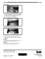
1.
Turn OFF the fireplace and allow it to cool before proceeding.
2.
If the appliance is connected to 120 volt power, disconnect
the power.
3.
If unit is a gas fireplace, shut OFF the gas supply to
the fireplace.
4.
Access the bottom compartment.
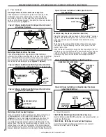
Wood-burning fireplaces with a louver panel
Push the two fireplace opening screens toward the middle of the
unit to expose the louver panel retaining screw at each end of the
panel. Remove the retaining screws and then pull the panel from
the unit.
Wood-burning fireplaces with a grille
Remove the bottom grille by lifting it up near its outer support
rods. It must be lifted high enough to clear the support rod
retaining holes located in the cabinet bottom flange. Then pull
the bottom of the grille away from the fireplace.
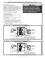
Elite-2 Series Legacy Gas Fireplaces
Remove the bottom door (panel or louvers) by sliding the hinge
pin, located at the door’s left side, to the right until it disengages
from the left corner post hole. Pull the door diagonally to the left,
away from the fireplace.
Remove the modesty panel by lifting the modesty panel by the
tab on the right end, then pulling the right end of the panel away
from cabinet. Pull the panel diagonally out of the corner post
slots on the left side of the unit. Remove the modesty panel
carefully, to make sure no wires become loose or disconnected.
Merit Legacy Gas Fireplaces
Remove the bottom panel or louvers by removing the screw at
each end of the panel or louvers, retain the end spacers, and
then pull the panel or the louvers from the unit.
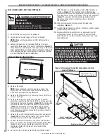
All Other Gas Fireplaces (except Elite Linear View)
Open the lower panel (clean face models) or louver assembly
(louvered models) by simultaneously pushing in the left and
right side of the panel or louver assembly.
P750028M


