background image

Quick Start Guide

–  2  –

Alignment

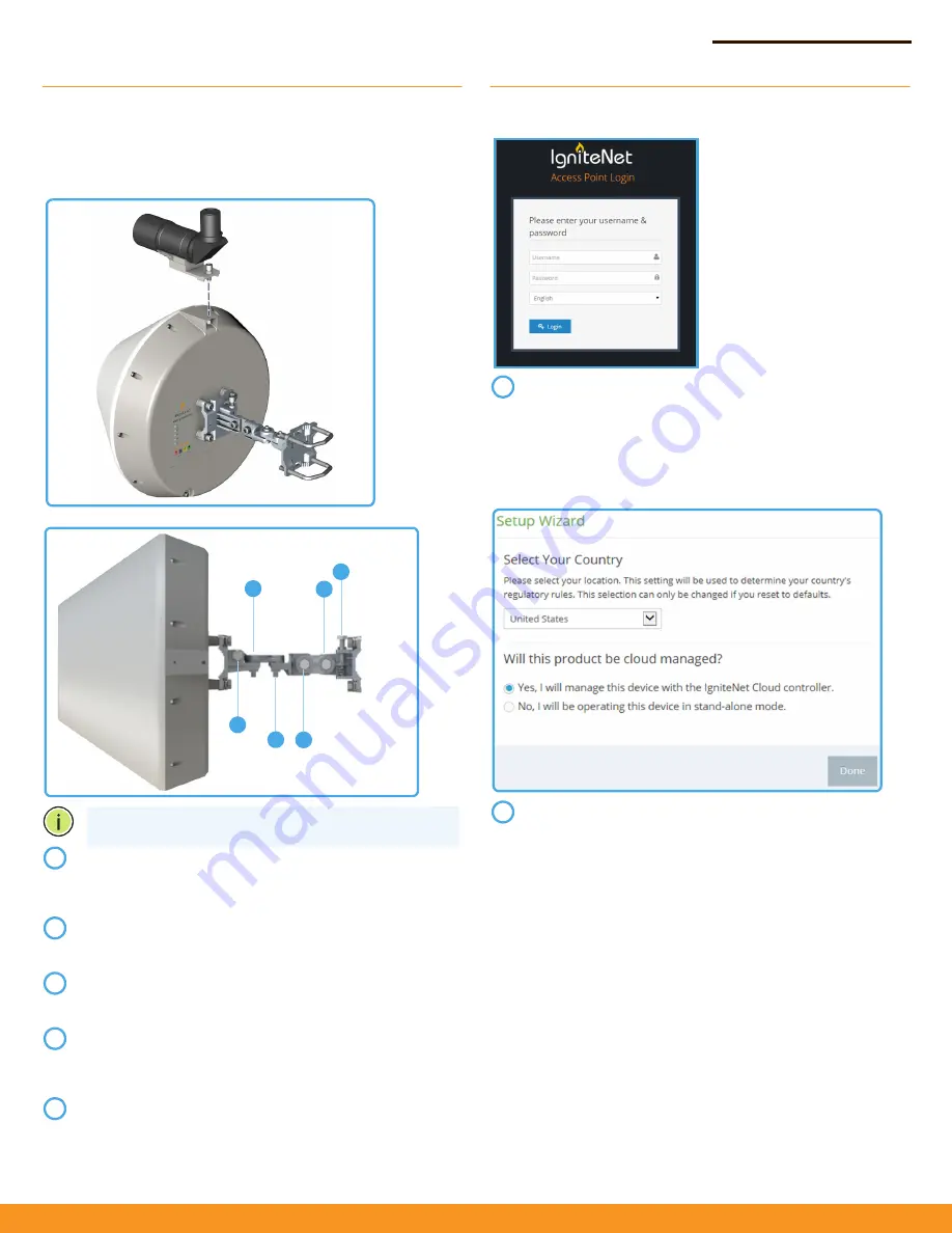
IgniteNet strongly recommends using the ICC-SCOPE-9x50 
Alignment Scope for alignment. To install, place the scope on top of 
the MetroLinq™ housing and secure it with its thumb screw.

Software

For more configuration details and training, please go to 
ignitenet.com/support

Note:

 Do not adjust bolts A and B without first loosening 1 

and 4 respectively.

Loosen coarse adjustment bolts 2 and 3 and set initial 

alignment. Don’tworry, you don’t have to be too accurate 

yet. After you have set the coarse alignment, tighten bolts 2 

and 3.

Loosen the horizontal fine-tune adjustment bolt 4. Use fine-

tune bolt "B" to optimize the horizontal position. Re-tighten 

bolt 4.

Loosen the vertical fine-tune adjustment bolt 1. Use fine-

tune bolt "A" to optimize the vertical position. Re-tighten 

bolt 1.

Initial alignment should be based on optical or visual 

alignment. After you achieve this, repeat steps 2 and 3 while 

watching the 60 GHz signal strength LED. Optimize position 

to the LED indicator.

Ensure all bolts are fully tightened, remove the alignment 

scope (if installed), and enjoy Gigabit interference-free 

wireless.

2

1

4

A

2

3

B

1

2

3

4

5

To configure your MetroLinq, connect your computer to the 

LAN port on the device and configure the IP subnet to 

match the default IP address of 192.168.1.20 Once 

configured, direct your web browser to 192.168.1.20 and log 

in.
username: root

password: admin123

After you have logged in, follow the steps in the Setup 

Wizard to configure the device for your network.

1

2

Summary of Contents for ML-60-19

Page 1: ...what is best for your location and select hardware accordingly Power Up Welcome to MetroLinq Interference Free Gigabit Wireless Ensure all four position locking bolts are tight before installing 1 In...

Page 2: ...l position Re tighten bolt 4 Loosen the vertical fine tune adjustment bolt 1 Use fine tune bolt A to optimize the vertical position Re tighten bolt 1 Initial alignment should be based on optical or vi...

Page 3: ...needs to be installed by a qualified person who has RF and related rules knowledge The general user shall not attempt to install or change the settings 2 Installation location The product shall be in...

Page 4: ...or network and service supply not for spectrum Norway Implemented This subsection does not apply for the geographical area within a radius of 20 km from the centre of Ny lesund Russian Federation None...

Page 5: ...e e Radio LAN device sp a z kladn po iadavky a v etky pr slu n ustanovenia Smernice 1999 5 ES Slovenian Slovensko IgniteNet izjavlja da je ta radio LAN device v skladu z bistvenimi zahtevami in ostali...

Page 6: ...N RJ 45 Port 1000BASE T 60 GHz Radio IEEE 802 11ad 5 GHz Radio IEEE 802 11ac Radio Frequencies 5150 5250 MHz FCC 5725 5850 MHz FCC 5745 5825 MHz China 5180 5320 MHz ETSI 5500 5700 MHz ETSI 58 32 64 80...

Page 7: ...e separation between the equipment and receiver Connect the equipment into an outlet on a circuit different from that to which the receiver is connected Consult the dealer or an experienced radio TV t...

Page 8: ...in normal operation condition to meet regulatory RF exposure requirement 3 External antenna Use only the antennas which have been approved by the applicant The non approved antenna s may produce unwa...

Page 9: ...pas tre co localis s ou fonctionnement en association avec une autre antenne ou transmetteur This radio transmitter IC 3857A ML6035G3 has been approved by Industry Canada to operate with the antenna...

Page 10: ...p cifi e pour l exploitation point point et non point point selon le cas Users should also be advised that high power radars are allocated as primary users i e priority users of the bands 5250 5350 MH...

Reviews: