background image

Quick Start Guide

– 2  –

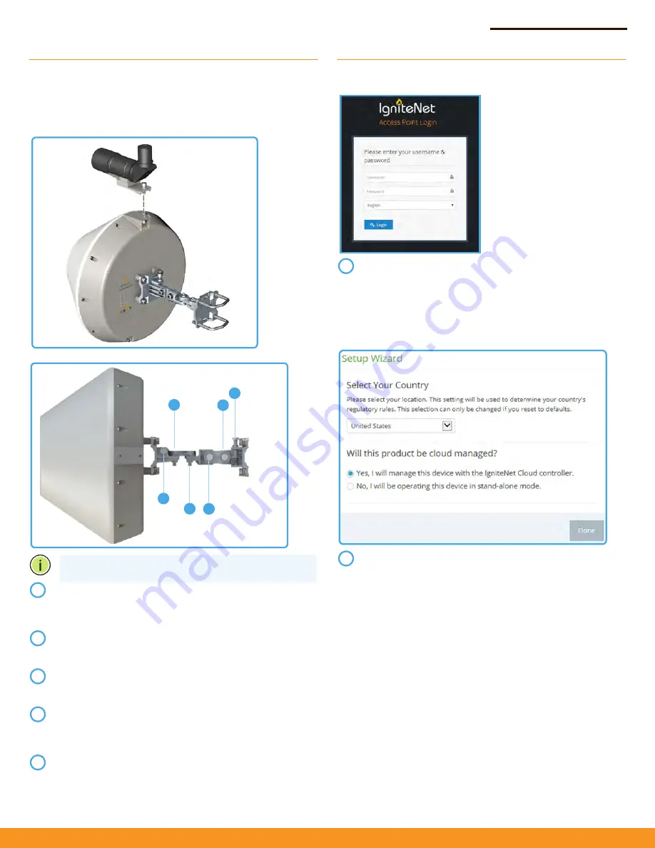
Alignment

IgniteNet strongly recommends using the ICC-SCOPE-9x50 
Alignment Scope for alignment. To install, place the scope on top 
of the MetroLinq housing and secure it with its thumb screw.

Software

For more configuration details and training, please go to 
ignitenet.com/support

Note:

 Do not adjust bolts A and B without first loosening 1 

and 4 respectively.

Loosen coarse adjustment bolts 2 and 3 and set initial 
alignment. Don’tworry, you don’t have to be too accurate 
yet. After you have set the coarse alignment, tighten bolts 2 
and 3.

Loosen the horizontal fine-tune adjustment bolt 4. Use fine-
tune bolt "B" to optimize the horizontal position. Re-tighten 
bolt 4.

Loosen the vertical fine-tune adjustment bolt 1. Use fine-
tune bolt "A" to optimize the vertical position. Re-tighten 
bolt 1.

Initial alignment should be based on optical or visual 
alignment. After you achieve this, repeat steps 2 and 3 while 
watching the 60 GHz signal strength LED. Optimize position 
to the LED indicator.

Ensure all bolts are fully tightened, remove the alignment 
scope (if installed), and enjoy Gigabit interference-free 
wireless.

2

1

4

A

2

3

B

1

2

3

4

5

To configure your MetroLinq, connect your computer to the 
LAN port on the device and configure the IP subnet to 
match the default IP address of 192.168.1.20 Once 
configured, direct your web browser to 192.168.1.20 and log 
in.
username: root
password: admin123

After you have logged in, follow the steps in the Setup 
Wizard to configure the device for your network.

1

2

Summary of Contents for MetroLinq2.5 ML2.5-60-19

Page 1: ...our location and select hardware accordingly Power Up Welcome to MetroLinq Interference Free Gigabit Wireless Ensure all four position locking bolts are tight before installing 1 Install the bracket o...

Page 2: ...l position Re tighten bolt 4 Loosen the vertical fine tune adjustment bolt 1 Use fine tune bolt A to optimize the vertical position Re tighten bolt 1 Initial alignment should be based on optical or vi...

Page 3: ...with FCC radiation exposure limits set forth for an uncontrolled environment This equipment should be installed and operated with minimum distance 48 cm between the radiator and your body Note The co...

Page 4: ...or network and service supply not for spectrum Norway Implemented This subsection does not apply for the geographical area within a radius of 20 km from the centre of Ny lesund Russian Federation None...

Page 5: ...adio LAN device sp a z kladn po iadavky a v etky pr slu n ustanovenia Smernice 1999 5 ES Slovenian Slovensko IgniteNet izjavlja da je ta radio LAN device v skladu z bistvenimi zahtevami in ostalimi re...

Page 6: ...PoE LAN RJ 45 Port 1000BASE T 60 GHz Radio IEEE 802 11ad 5 GHz Radio IEEE 802 11ac Radio Frequencies 5150 5250 MHz FCC 5725 5850 MHz FCC 5745 5825 MHz China 5180 5320 MHz ETSI 5500 5700 MHz ETSI 58 32...

Page 7: ...e following measures Reorient or relocate the receiving antenna Increase the separation between the equipment and receiver Connect the equipment into an outlet on a circuit different from that to whic...

Page 8: ...t type are strictly prohibited for use with this device Le pr sent metteur radio IC 3857A ML2560 a t approuv par Industrie Canada pour fonctionner avec les types d antenne num r s ci dessous et ayant...

Page 9: ...ment This equipment should be installed and operated with minimum distance 69 cm between the radiator your body Cet quipement est conforme aux limites d exposition aux rayonnements IC tablies pour un...

Reviews: