Operating instructions
Electronic pressure sensor
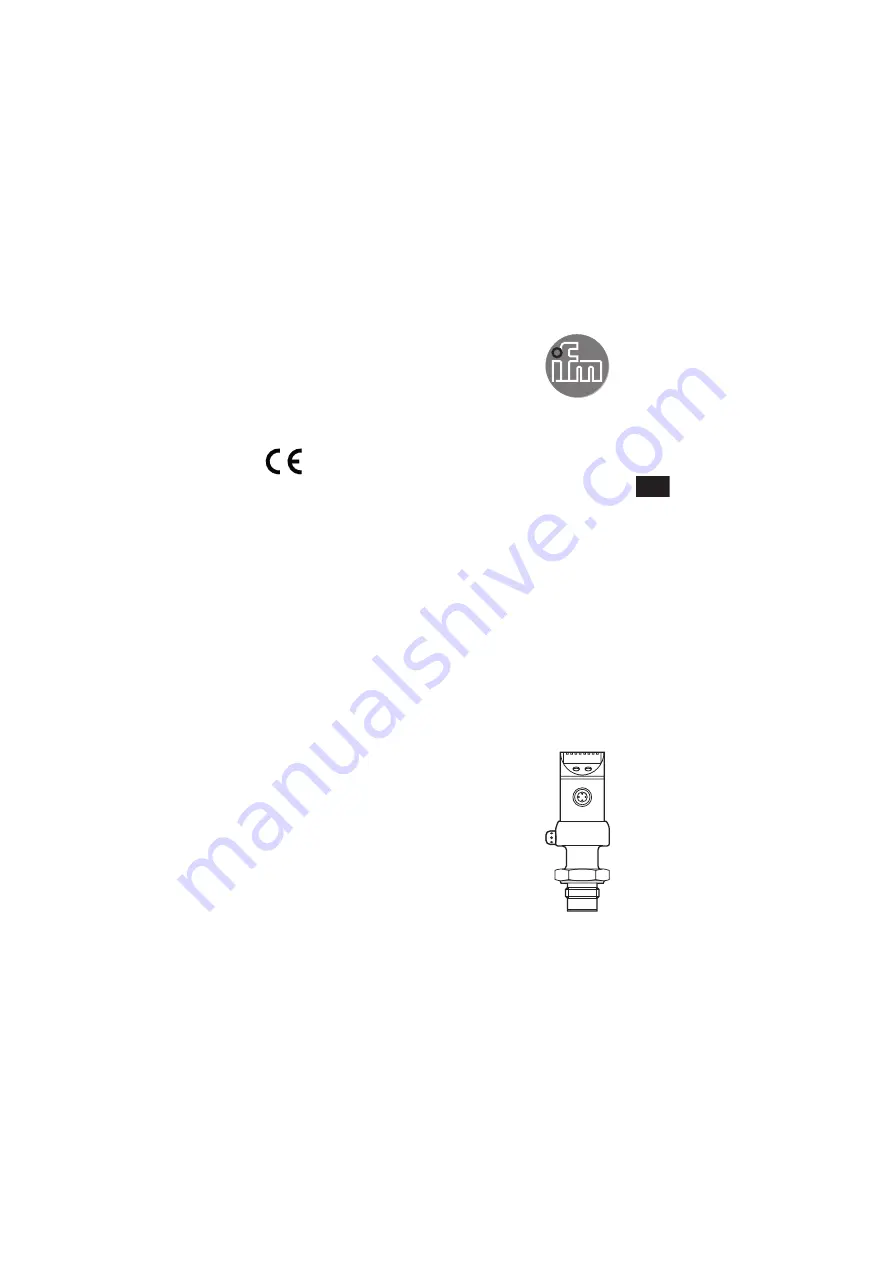
PI299x
UK
11426178 / 00
07 / 2016
Page 1: ...Operating instructions Electronic pressure sensor PI299x UK 11426178 00 07 2016...
Page 2: ...rameter setting 14 9 1 Parameter setting general 14 9 2 Configuring the display optional 16 9 3 Setting the output signal 16 9 3 1 Setting the output function 16 9 3 2 Setting the switching limits 17...
Page 3: ...must contain all necessary information and safety instructions for the operator the user and if applicable for any service personnel authorised by the manufacturer of the system Read this document bef...
Page 4: ...pressure rating and bursting pressure data sheet Static and dynamic overpressures exceeding the indicated overload pressure are to be avoided by taking appropriate measures The indicated bursting pre...
Page 5: ...rmally open OU1 Hno fig 1 Hysteresis function normally closed OU1 Hnc fig 1 First the set point SP1 is set then the reset point rP1 at the requested distance Window function normally open OU1 Fno fig...
Page 6: ...define the measured value at which the output signal is 4 mA 0 V 20 mA 10 V at InEG UnEG By teaching the analogue end point tAEP or setting the parameter AEP you define the measured value at which th...
Page 7: ...Voltage output Factory setting Measuring range scaled P system pressure MAW initial value of the measuring range MEW final value of the measuring range 1 OU2 U 2 OU2 UnEG The output signal is between...
Page 8: ...trinsic temperature of the unit too high 100 C too low 30 C RAM fault 5 Installation Ensure that no pressure is applied to the installation while mounting or removing the sensor Please note Display 0...
Page 9: ...rectly positioned Screw the unit into the adapter E until it is hand tight fig 2 Do not damage the sealing chamfers Clamp sensor and adapter into a clamping device F fig 3 Tighten the clamping device...
Page 10: ...ment must be adhered to Voltage supply to EN50178 SELV PELV Disconnect power Connect the unit as follows OUT1 p switching OUT1 n switching Pin 1 Ub Pin 3 Ub Pin 4 OUT1 binary switching output for pres...
Page 11: ...7 not used LED 8 switching state of the output LED lights if output 1 is switched 9 Alphanumeric display 4 digits Indication of the current system pressure Indication of the parameters and parameter...
Page 12: ...12 8 Menu 8 1 Menu structure...
Page 13: ...10 V are output 4 mA 0 V on OU2 InEG UnEG EF Extended functions Opening menu level 2 Uni Standard unit of measurement for the system pressure SELd Display mode Pressure in the unit set in Uni Pressur...
Page 14: ...of the parameter bit flashes for 5 s After 5 s Setting value is changed incremental by pressing briefly or scrolling by holding pressed The numerical values are incremented continuously If the value...
Page 15: ...by ifm electronic no access restriction Locking unlocking The unit can be locked electronically to prevent unintentional wrong settings Ensure that the unit is in the normal operating mode Press Mode...
Page 16: ...by 180 OFF The display is deactivated in the operating mode If one of the buttons is pressed the current measured value is displayed for 15 s Another press of the Mode Enter button opens the Display m...
Page 17: ...n the system Press Mode Enter until tAEP is displayed Press Set and keep the buton pressed The currently set value flashes Release Set when the display stops flashing The new set value is displayed Pr...
Page 18: ...d Release Set Press Mode Enter briefly to confirm the new offset value 9 4 2 Setting the delay time for OUT1 dS1 switch on delay dr1 switch off delay Select dS1 or dr1 and set the value between 0 1 an...
Page 19: ...on It carries out its measurement and evaluation functions and generates output signals according to the set parameters Operating indicators chapter 7 Operating and display elements 10 1 Read the set...
Page 20: ...Unscrew the filter cover B use a pair of pliers with plastic covered jaws for this Clean the cover thoroughly The vent A should only be cleaned by skilled personnel and with utmost care Possible mediu...
Page 21: ...MR rP1 23 VMR ASP tASP 0 VMR AEP tAEP 100 VMR COF tCOF 0 0 dS1 0 0 dr1 0 0 P n pnp dAP 0 1 dAA 0 1 Uni bAr mbAr SELd P dis d2 the indicated percentage of the final value of the measuring range VMR of...