background image

21

UK

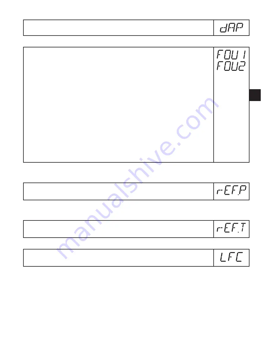
9.5.3  Setting of measured value damping


Select [dAP] and set the damping constant in seconds (t value 63 %)�

9.5.4  Setting of the error behaviour of the outputs


Select [FOU1] and set the value

 -[On] = output 1 switches ON in case of a fault�

 -[OFF] = output 1 switches OFF in case of a fault�


> For both values ([ON] and [OFF]) the counter stops counting in case of 

a fault�

 -[OU] = output 1 switches irrespective of the error as defined with the 

parameters�


Select [FOU2] and set the value

 -[On] = output 2 switches ON in case of a fault, the analogue signal 

goes to the upper end stop value (22 mA)�

 -[OFF] = output 2 switches OFF in case of a fault, the analogue signal 

goes to the lower end stop value (3�5 mA)�

 -[OU] = output 2 switches irrespective of the error as defined with 

the parameters� The curve of the analogue signal corresponds to 

IEC60947-5-7 (→ diagram in 4.6).

9.5.5  Setting of the standard pressure to which the measured and display 

values for volumetric flow refer


Select [rEF�P] and set the requested standard pressure�

Setting range: 950���1050 hPa in steps of 1 hPa�

9.5.6  Setting of the standard temperature to which the measured and dis-

play values for volumetric flow refer


Select [rEF�T] and set the requested standard temperature�

Setting range: 0���25 °C in steps of 1 °C�

9.5.7  Setting of the low flow cut-off


Select [LFC] and set the limit value�

Setting range: 0�3���2�3 Nm³/h in steps of 0�1 Nm³/h�

Summary of Contents for SD8000

Page 1: ...Operating instructions Compressed air meter SD8000 706094 01 03 2012 UK ...

Page 2: ...oring analogue function 8 4 7 Setting of the standard conditions of the volume flow 9 4 8 Low flow cut off LFC 9 5 Installation 10 5 1 Installation location 10 5 2 Installation conditions 10 5 3 Installation position 11 5 4 Installation in pipes 11 6 Electrical connection 12 7 Operating and display elements 13 8 Menu 14 8 1 Menu structure 14 8 2 Explanation of the menu 15 9 Parameter setting 16 9 ...

Page 3: ...f measured value damping 21 9 5 4 Setting of the error behaviour of the outputs 21 9 5 5 Setting of the standard pressure to which the measured and display values for volumetric flow refer 21 9 5 6 Setting of the standard temperature to which the measured and dis play values for volumetric flow refer 21 9 5 7 Setting of the low flow cut off 21 9 6 Service functions 22 9 6 1 Reading of the min max ...

Page 4: ... to Ensure before mounting the components into or removing them from the compressed air system that the installation is at a standstill and no pressure is applied Improper or non intended use may lead to malfunctions of the unit or to un wanted effects in your application That is why installation electrical connec tion set up operation and maintenance of the unit must only be carried out by qualif...

Page 5: ...low velocity limit value 9 2 2 or switching signal for temperature limit value 9 4 1 or analogue signal for volumetric flow quantity 9 2 3 or analogue signal for flow velocity 9 2 3 or analogue signal for temperature 9 4 2 Instead of an output OUT2 Pin2 can be used as an input for an external reset signal 9 3 5 4 2 Volumetric flow monitoring The flow is monitored by a calorimetric measuring system...

Page 6: ... 2 types of monitoring are possible Time dependent quantity monitoring Settings ImPS quantity X ImPR no rTo time t If the quantity x is reached during the time t output 1 switches and remains switched until the meter is reset via the digital input or rTo rED T In this case the time controlled totalizer reset is not carried out if ImPS quantity X exceeded If the quantity x is not reached during the...

Page 7: ... Hysteresis function normally closed figure 1 OUx Hnc First the set point SPx is set then the reset point rPx with the requested difference Note when SPx is adjusted rPx is changed automatically the differ ence remains constant Window function normally open fig 2 OUx Fno Window function normally closed figure 2 OUx Fnc The width of the window can be set by means of the difference between SPx and r...

Page 8: ...easuring range VMR 7 Error message OL is displayed overload 8 Analogue end point AEP determines at which measured value the output signal is 20 mA 9 Curve of the analogue signal with shifted analogue start point 10 Curve of the analogue signal at factory setting 11 Analogue start point ASP determines at which measured value the output signal is 4 mA 12 Error message UL is displayed underload 13 Er...

Page 9: ...t which serves as a refer ence for the measured and display values for volumetric flow 9 5 5 Via the menu item rEF T the standard temperature is set which serves as a reference for the measured and display values for volumetric flow 9 5 6 4 8 Low flow cut off LFC With this function small volumetric flow quantities can be suppressed 9 5 7 Flows below the LFC value have no effect on the display and ...

Page 10: ...nstallation conditions To achieve the specified measurement accuracy the following installation condi tions must be adhered to defined inlet and outlet pipe lengths defined flow cross section area fixed installation depth and correct positioning of the measuring elements The unit is mounted in a measuring range which meets these conditions In case of disturbances on the inflow side additional calm...

Page 11: ...tical fig 3 4 unit on side pipe length left fig 5 Avoid the installation position in fig 6 unit on side pipe length right If the flow rate is low the specified measurement accuracy cannot be adhered to 1 2 3 4 5 6 5 4 Installation in pipes Fit the unit in the pipe in accordance with the flow direction arrow on the unit and tighten IN OUT ...

Page 12: ...n 1 Ub Pin 3 Ub Pin 4 OUT1 Switching signal limit values for volumetric flow Switching signal quantity meter reached preset value Pulses 1 pulse every time the defined volumetric flow quantity is reached Data channel for bidirectional communication IO Link pin 2 OUT2 InD Switching signal limit values for volumetric flow Switching signal limit values for temperature Analogue signal for volumetric f...

Page 13: ...reset in 103 standard cubic metres values 9999 are displayed using the 103 exponential notation LED 5 green current medium temperature in C LED 7 yellow switching status of the corresponding output LED indicates the input status also with an active external reset LED 8 yellow switching status of the corresponding output 9 Alphanumeric display 4 digits Indication of the current volumetric flow quan...

Page 14: ... M S M M M S M S M S M S M Nl min S S Nm3 h S 15s S Nm s 15s S Nm3 15s S Nm3 15s C 15s M M M M M M M S M S M S M S M S S M S M S M M M M Mode Enter Set Nm3 current meter reading in Nm3 Nm3 stored meter reading in Nm The parameter values displayed in the form of numbers are factory settings or random examples ...

Page 15: ...etric flow or temperature DIn2 Configuration of the input Pin2 for counter reset EF Extended functions opening of menu level 2 HI LO Maximum minimum value memory for volumetric flow FOU1 Behaviour of output 1 in case of an internal fault FOU2 Behaviour of output 2 in case of an internal fault dAP Measured value damping damping constant in seconds rTo Counter reset manual reset time controlled rese...

Page 16: ...IODD and the FDT service program ifm Container can be downloaded at www ifm com Service Download 9 1 General parameter setting 3 steps must be taken for each parameter setting 1 Parameter selection Press Mode Enter until the re quested parameter is displayed 2 Setting of the parameter value Press Set and keep it pressed Current setting value of the param eter flashes for 5 s After 5 s setting valu...

Page 17: ...moved via a parameter setting software Change from menu level 1 to menu level 2 Press Mode Enter until EF is displayed Press Set briefly The first parameter of the submenu is displayed here HI Locking unlocking The unit can be locked electronically to prevent unintentional settings Make sure that the unit is in the normal operating mode Press Mode Enter Set for 10 s Loc is displayed During operati...

Page 18: ... function NO Fnc window function NC Select SP2 and set the value at which the output switches Select rP2 and set the value at which the output switches back 9 2 3 Setting the analogue value for volumetric flow Select Uni and set the unit of measurement 9 5 1 Select SEL2 and set FLOW Select OU2 and set the function I current signal proportional to volumetric flow 4 20 mA Select ASP and set the valu...

Page 19: ...ter the value for time controlled reset Press Set until the requested value is displayed intervals from 1 hour to 8 weeks then briefly press Mode Enter Press Set until rES T is displayed then briefly press Mode Enter 9 3 4 Deactivation of the counter reset Select rTo and set OFF The meter is only reset after overflow fac tory setting Overflow After the maximum value 9 999 999 Nm the counter is res...

Page 20: ...umetric flow Select Uni and set the unit of measurement Lmin volumetric flow quantity in standard litres minute nm3h volumetric flow quantity in standard cubic metres hour nmS current flow velocity in standard metres second The setting only has an effect on the volumetric flow value 9 5 2 Configuration of the standard display Select SELd and determine the standard measuring unit FLOW the current v...

Page 21: ... switches OFF in case of a fault the analogue signal goes to the lower end stop value 3 5 mA OU output 2 switches irrespective of the error as defined with the parameters The curve of the analogue signal corresponds to IEC60947 5 7 diagram in 4 6 9 5 5 Setting of the standard pressure to which the measured and display values for volumetric flow refer Select rEF P and set the requested standard pre...

Page 22: ...ter briefly For the factory settings please refer to the end of these instructions 13 Factory setting We recommend taking down your own settings in that table before carrying out a reset After reset to factory setting the value of the memory is set at zero 9 7 Setting of the preset counter the pulse value ImPS The unit has 7 setting ranges LED Display Step increment Setting range 1 4 0 0 0 3 9 9 9...

Page 23: ...n all 4 digits are set As soon as the first digit flashes there are 3 options Briefly press Set 1 x The flashing digit increments 9 is followed by 0 1 2 etc 8 1 2 3 SET pressed 1 x 9 1 2 3 SET pressed 1 x 0 1 2 3 SET pressed 1 x 1 1 2 3 Press Set and keep it pressed The flashing digit increments 9 is followed by 0 and the next digit on the left becomes active 8 1 7 3 Set permanently pressed 8 1 9 ...

Page 24: ...o the start value After this release Set briefly and start the setting again 10 Operation Correct operation and compliance with the measurement accuracy can only be ensured if the environmental conditions specified in the technical data 12 are adhered to Ensure that the maximum pressure range measuring range and permitted operating temperature are not exceeded After power on and expiry of the powe...

Page 25: ... OUT1 SC2 Short circuit in OUT2 SC Short circuit in both outputs OL Measured value 120 of the final value of the measuring range UL Measured value 20 of the final value of the measuring range temperature Err Flashing error in the measuring probe or measured value 130 of the final value of the measuring range The output concerned is switched off as long as the short circuit exists These messages ar...

Page 26: ...26 11 Scale drawing Dimensions in mm 1 Programming buttons 2 Display 3 LEDs ...

Page 27: ...red value 0 6 final value of the measuring range 4 Repeatability of the measured value 1 5 Measurement dynamics 1 300 Response time s 0 1 dAP 0 Temperature monitoring Measuring range C 0 60 Display range C 12 72 Response time s T09 30 Q 0 1 Nm Resolution C 0 5 Accuracy C 2 5 Q 0 1 Nm 5 Ambient temperature C 0 60 Medium temperature C 0 60 rel humidity max 90 Storage temperature C 20 85 Pressure res...

Page 28: ...fer to the standard volume flow to DIN ISO 2533 12 1 Setting ranges FLOW SP1 SP2 rP1 rP2 ASP AEP Q min max min max min max min max Nl min 30 3750 12 3732 0 2813 937 3750 1 Nm3 h 1 8 225 0 0 7 223 9 0 0 168 8 56 2 225 0 0 1 Nm s 0 9 109 2 0 4 108 7 0 0 81 9 27 3 109 2 0 1 TEMP SP2 rP2 ASP AEP T min max min max min max min max C 0 4 60 0 0 2 59 8 0 0 45 0 15 0 60 0 0 2 ImPS min max 0 003 Nm3 3 000 0...

Page 29: ...0 003 ImPR YES OU1 Hno OU2 I SP2 FLOW 90 0 rP2 FLOW 88 9 SP2 TEMP 24 0 rP2 TEMP 23 8 ASP FLOW 0 0 AEP FLOW 225 0 ASP TEMP 0 0 AEP TEMP 60 0 DIn2 EDG FOU1 OFF FOU2 OFF dAP 0 6 rTo OFF diS d3 Uni nm3h SELd FLOW SEL2 FLOW rEF P 1013 rEF T 15 LFC 0 3 More information at www ifm com ...

Reviews: