


21
UK
Operation
8
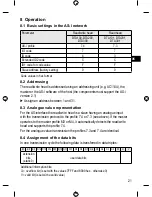
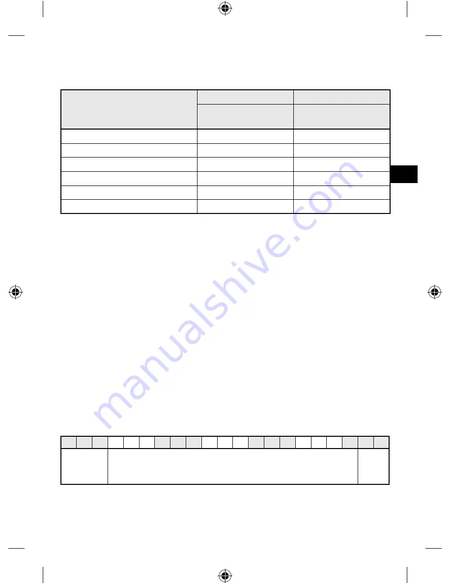
Basic settings in the AS-i network
8.1
Parameter
Read/write head
Read head
DTA100, DTA200,
DTA300
DTA101, DTA201,
DTA301
AS-i profile
7.4
7.3
I/O code
7
7
ID code
4
3
Extended ID2 code
C
C
ID1 code for code value
F
F
Slave address (factory setting)
0
0
Code values in hex format
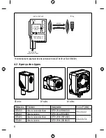
Addressing
8.2
The read/write head is addressed using an addressing unit (e.g. AC1144), the
master or the AS-i software of the host (the components must support the AS-i
version 2.1).
Assign an address between 1 and 31.
►
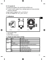
Analogue value representation
8.3
For the AS-interface the read/write head is a slave having an analogue input
with the transmission protocol to the profile 7.4 or 7.3 (see above). If the master
operates to the master profile M3 or M4, it automatically detects the read/write
head and supports the profile 7.4.
For the analogue value transmission the profiles 7.3 and 7.4 are identical.
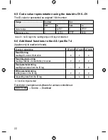
Assignment of the data bits
8.4
In one transmission cycle the following data is transferred in data triples:
E1 E2
E3 D16 D15 D14 D13 D12 D11 D10 D9 D8 D7 D6 D5 D4 D3 D2 D1
O
V
extension
bits
(static 0)
user data bits
Additional information bits:
O = overflow bit (is set with the values 7FFF and 8000 hex., otherwise 0)
V = valid bit (is set with a valid value)


