35
36
37
38
42
41
39
30
46
44
40
43
32
33
29
5
10
16
17
11
6
34
8
7
31
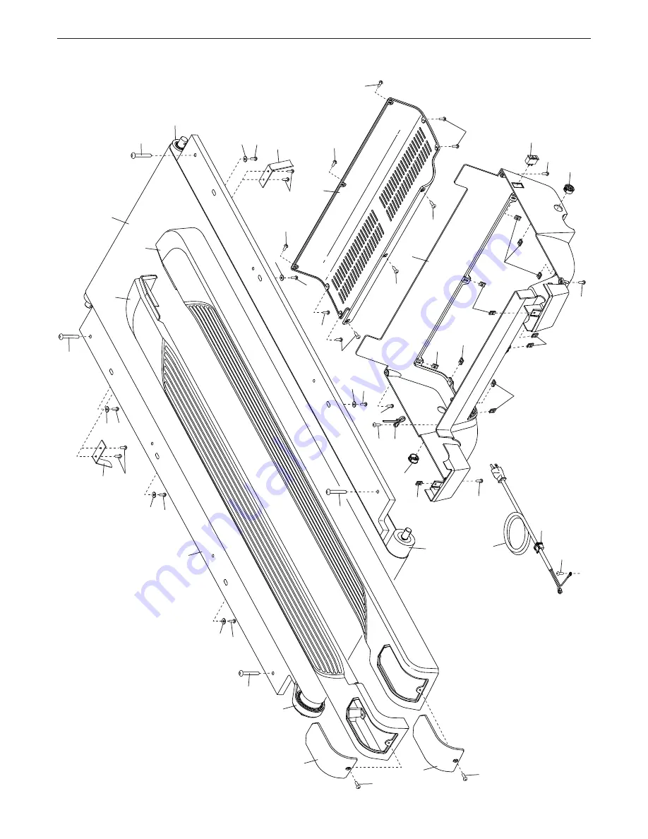
EXPLODED DRAWING A
Model No. NTL39221.1 R1022A
Page 1: ...cautions and instructions in this manual before using this equipment Keep this manual for future reference Serial Number Decal REGISTER YOUR PRODUCT MEMBER CARE To register your product and activate y...
Page 2: ...NTY Back Cover This drawing shows the locations of the warning decals If a decal is missing or illegible see the front cover of this manual and request a free replacement decal Apply the decal in the...
Page 3: ...re oxygen is being administered 11 The incline trainer should be used only by persons weighing 300 lbs 136 kg or less 12 Never allow more than one person on the incline trainer at a time 13 Wear appro...
Page 4: ...move the key press the power switch into the off position see the drawing on page 6 for the location of the power switch and unplug the power cord when the incline trainer is not in use 25 Do not atte...
Page 5: ...5 all STANDARD SERVICE PLANS...
Page 6: ...he front cover To help us assist you note the product model number and serial number before contacting us The model number and the location of the serial number decal are shown on the front cover of t...
Page 7: ...ey number of the part from the PART LIST near the end of this manual The number following the key number is the quantity used for assembly Note If a part is not in the hardware kit check to see whethe...
Page 8: ...r This is normal If there is an oily substance on the incline trainer wipe it off with a soft cloth and a mild non abra sive cleaner To identify small parts see page 7 Assembly requires the following...
Page 9: ...ight side Attach the right Upright 83 with two of the 3 8 x 3 1 4 Screws 18 and two of the 3 8 x 2 3 4 Screws 22 that you just removed and four 3 8 Star Washers 3 do not fully tighten the Screws yet M...
Page 10: ...ottom 109 to the right handrail assembly D in the same way C D 108 5 Connect the Base Wire 52 to the Upright Wire 75 IMPORTANT The wire connectors should slide together easily and snap into place with...
Page 11: ...second person hold the handrail assembly E below the Console 93 as shown Then move both sides of the hand rail assembly upward at the same time sliding the inner corner F of the handrail assem bly be...
Page 12: ...E THE INCLINE TRAINER on page 27 After the incline trainer is placed in the loca tion where it will be used make sure that the incline trainer rests firmly on the floor If the incline trainer rocks ev...
Page 13: ...to a surge suppressor A and plug the surge suppressor into an appropri ate outlet D that is properly installed and grounded in accordance with all local codes and ordinances The outlet must be on a no...
Page 14: ...patible heart rate monitor see page 25 The console also features wireless technology that enables the console to connect to iFIT With iFIT you can choose from a rotating selection of featured work out...
Page 15: ...s To find which unit of measurement is selected see HOW TO CHANGE CONSOLE SETTINGS on page 22 HOW TO TURN OFF THE CONSOLE When you are finished using the incline trainer first remove the key from the...
Page 16: ...not be described in this manual Also some settings and features described in this manual may no longer be enabled Take time to explore the console to learn how new settings and features work 5 Calibr...
Page 17: ...press two numbered buttons in succession For example to select a speed setting of 3 5 mph press the 3 but ton and then immediately press the 5 button Note This feature will not function when the conso...
Page 18: ...URE 1 Insert the key into the console See HOW TO TURN ON THE CONSOLE on page 15 Note It may take up to a few minutes for the console to be ready for use 2 Select the home screen See step 2 on page 17...
Page 19: ...ng your progress Touch the buttons on the screen to select the desired map options If the speed and or incline level is too high or too low you can manually override the setting by pressing the button...
Page 20: ...earch box or by sliding your fingers on the screen Touch the screen to add the start point for the workout Then touch the screen to add the end point for the workout If you want to start and end the w...
Page 21: ...wse button To select an iFIT workout from the home screen or the workout library simply touch the desired work out button on the screen Slide or flick the screen to scroll upward or downward if necess...
Page 22: ...nd features work 1 Select the settings main menu First turn on the console and insert the key into the console see HOW TO TURN ON THE CONSOLE on page 15 Note It may take up to a few min utes for the c...
Page 23: ...do not press the power switch or unplug the power cord while the firmware is being updated The screen will show the progress of the update When the update is complete the console will turn off and th...
Page 24: ...Fi is enabled the screen will show a list of available networks Note It may take a few moments for the list of wireless networks to appear Note You must have your own wireless network and an 802 11b g...
Page 25: ...on the screen When your headphones and the console pair successfully the audio from the console will play through your headphones HOW TO USE AN OPTIONAL HEART RATE MONITOR Whether your goal is to burn...
Page 26: ...and on try to correct the interference by one or more of the following measures Reorient or relocate the receiving antenna Increase the separation between the equipment and the receiver Connect the e...
Page 27: ...r of damage to the incline trainer do not lift the incline trainer by the plastic belly pan D Do not pull on the console Carefully roll the incline trainer on the wheels to the desired location and th...
Page 28: ...operly grounded outlet see page 13 Use only a surge suppressor that meets all of the specifications described on page 13 IMPORTANT If the incline trainer is connected to an AFCI equipped outlet and yo...
Page 29: ...a hex key in the two indicated locations D and turn the hex key in quarter turn increments until the console is tightened SYMPTOM The displays of the console do not function properly a If the console...
Page 30: ...ase see the Member Care contact information on page 28 d If the walking belt still slows when walked on please see the Member Care contact information on page 28 SYMPTOM The walking belt is off center...
Page 31: ...ystem you must perform aerobic exercise which is activity that requires large amounts of oxygen for prolonged periods of time For aerobic exercise adjust the intensity of your exercise until your hear...
Page 32: ...lles Stretch With one leg in front of the other reach forward and place your hands against a wall Keep your back leg straight and your back foot flat on the floor Bend your front leg lean forward and...
Page 33: ...t Rail Cover 44 1 Left Foot Rail Cover 45 4 Small Pivot Bushing 46 1 Drive Belt 47 1 Front Hood 48 1 Front Belly Pan 49 8 Cushion Cap 50 4 Spring 51 4 Cushion 52 1 Base Wire 53 4 Rubber Cushion 54 2 L...
Page 34: ...16 x 3 4 Screw 103 8 5 16 Star Washer 104 2 8 x 2 Screw 105 6 8 x 1 1 4 Screw 106 6 8 x 5 8 Machine Screw 107 2 3 8 x 1 2 Screw 108 4 5 16 x 3 4 Patch Screw 109 1 Push Bar Bottom 110 1 Push Bar Top 1...
Page 35: ...36 37 38 35 42 38 41 39 30 46 44 40 43 32 33 29 29 5 10 10 5 5 5 16 16 16 16 16 16 5 16 17 5 5 5 11 6 11 10 10 10 10 34 11 11 6 5 5 5 5 5 5 8 8 8 8 8 8 7 31 EXPLODED DRAWING A Model No NTL39221 1 R102...
Page 36: ...17 17 23 53 54 27 115 116 116 117 117 118 118 118 25 27 25 53 49 50 51 49 27 53 25 17 17 17 13 13 4 4 5 5 5 5 55 49 47 66 53 48 50 51 49 63 64 49 50 51 49 49 50 51 49 28 13 13 56 60 58 5 17 17 14 59 5...
Page 37: ...37 EXPLODED DRAWING C Model No NTL39221 1 R1022A 68 21 78 77 69 12 79 80 81 81 52 12 45 45 45 45 26 21 26 70 71 72 76 79 77 78 74 52 76 76 72 9 9 73 73 9 9 73 73...
Page 38: ...3 3 3 22 18 3 22 3 3 18 75 18 1 1 3 17 1 1 3 22 3 18 3 102 103 103 103 103 102 102 102 3 3 5 5 5 5 83 102 105 105 105 105 90 89 99 98 5 5 5 105 109 106 106 106 106 106 106 5 5 110 104 112 104 108 108...
Page 39: ...39 EXPLODED DRAWING E Model No NTL39221 1 R1022A 88 101 101 67 67 67 5 41 41 41 41 24 92 91 5 5 5 5 5 5 5 5 5 5 5 5 5 4 5 4 5 5 5 5 5 5 5 95 96 95 96 5 5 5 94 7 7 7 7 5 93...
Page 40: ...product is purchased or transported outside the USA 3 if any instruction or warning in this manual is not followed 4 if the product is abused or improperly or abnormally used 5 if the product is modif...