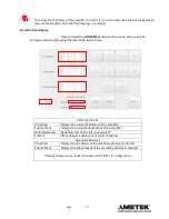
background image


                                                                   Page 


25


1.7


REMOTE EXAMPLE CODE 


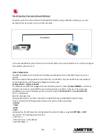
RS-232 USB or Ethernet, Example using Hyper-terminal 

 
1.


Connect serial port of amplifier to computer using a null modem cable or a standard serial 
cable with a null modem adapter. 

2.


Use a program such as Hyper-terminal to communicate with the amplifier. (To find Hyper-
terminal go to Start 

 Programs 

 Accessories 

 Communications 

 Hyper Terminal, 

and click on Hyper terminal.  


To setup Hyper terminal follow the directions below. 


When Hyper terminal runs a setup dialog box will open: 


For RS-232


2.1


Enter a name and choose an icon.  Click OK. 

2.2


In the Connect Using box select your Comm. port (Ex. “Direct to Com1” or 
“Com1”) for RS-232 or TCP/IP for Ethernet remote.  Click OK. 

2.3


In Bits per Second select “9600”.  

2.4


In Data Bits select “8”. 

2.5


In Parity Select “None”. 

2.6


In Stop bits select “1”. 

2.7


In Flow control select “None” 

2.8


Click OK. 


For Ethernet

:  


2.1


Enter a name and choose an icon.  Click OK. 

2.2


In the Connect Using box select TCP/IP for Ethernet remote. Click OK. 

2.3


Enter an 

IP Address

 in Host Address box and 

10001

 in Port Number box. Click 

OK.  


3.


 If you use Hyper-terminal steps 2.1 to 2.8 will set up Com1 to communicate at 9600 baud, 
8  bits,  and  no  parity  with  1  stop  bit  and  steps  2.1  to  2.3  will  set  up  Ethernet  to 
communicate at 57600 baud. 

4.


Turn amplifier line power ON. 

5.


To place the amplifier in remote operation type in a valid command such as “STATUS” 
and  then  hit  the  “Enter”  key.  The  amplifier  will  then  go  into  remote  operation  and  the 
status will be displayed on the computer. 


Summary of Contents for T188-250

Page 1: ...ruments for Industry 903 South Second Street Ronkonkoma NY 11779 Phone 631 467 8400 Fax 631 467 8558 Email OPERATING AND MAINTENANCE INSTRUCTIONS MODEL T188 250 HIGH POWER TWT AMPLIFIER DOCUMENT NUMBE...

Page 2: ...Warnings 17 5 2 Features 17 6 0 IEEE 488 INTERFACE OPTION 6 1 Introduction 18 6 2 Remote Initialization 18 6 3 GPIB Address 18 6 4 IEEE 488 Commands 19 6 5 RS 232 21 7 0 MAINTENANCE AND SERVICING 7 1...

Page 3: ...e and trouble free operation depends on you thoroughly reading through this manual and familiarizing yourself with its proper operation and usage Your Wide Band Amplifier comes with the following acce...

Page 4: ...t displays continuous forward and reflected power metering The display also provides the operator with operating status and self diagnostic fault indications The Amplifier incorporates protection circ...

Page 5: ...warranty shall not apply to any IFI product that has been disassembled modified physically or electrically damaged or any product that has been subjected to conditions exceeding the applicable specif...

Page 6: ...d to amplify a low level microwave signal and supply a high power CW output The Amplifier system function is accomplished primarily through the use of a Traveling Wave Tube TWT control circuitry and p...

Page 7: ...t supplies The Helix supply provides the negative high voltage potential between TWT Cathode and ground The Collector supply provides the high voltage potential between the TWT Cathode and Collector T...

Page 8: ...supply voltage output is monitored and displayed Should any power supply voltage deviate from the design parameters the Power Supply Fault Indication LED RED located on the front panel of the Amplifi...

Page 9: ...N OFF Ckt Bkr AC PWR IEC or MS Power Connector Touchscreen Display USB RF Input N Type Female IEEE 488 Connector FWD Sample Port N Type Female RS232 Remote Control Ethernet Remote Control Interlock RF...

Page 10: ...selection can be done through the front panel using the touchscreen display Holding the GPIB softkey will change the address BAND 1 BAND 2 OPT129 This optional feature allows the use of an Harmonic F...

Page 11: ...IONS A Apply power to the unit using the front panel ON OFF switch After 5 secs the splash screen will display Once it displays the Boot up will start Figure 4 0 Front Panel Display Splash Screen Figu...

Page 12: ...Up Menu After Boot up the Start up Menu will show and the amplifier can be controlled either Remotely or Manually Figure 5 is a typical screen customized to the amplifier Figure 5 0 Front Panel Displ...

Page 13: ...rting with the required time for the applicable TWT incorporated in the amplifier In this mode the Filament and Grid if applicable supplies will be energized 2 After the time out the High Voltage supp...

Page 14: ...STANDBY MODE Typical 1 Place the unit in OPERATE OPR mode In this mode the TWT will be turned ON 2 The display will show the Helix and Collector currents as per TWT operating data sheet FIGURE 9 0 OP...

Page 15: ...l the amplifier the FLT RST softkey must be pressed This will put the amplifier in the OFF Mode and you must restart the amplifier Soft Faults such as VSWR Limit or Interlock Open will only show up in...

Page 16: ...ction Band 1 is usually configured as the through Band This is done as protection so the filter is not driven out of Band Band 2 is the Harmonic Filter Band The Band Frequency limits will be displayed...

Page 17: ...er using a calibrated 50 Ohm Pad to assist the operator in maximizing the performance of the Wide Band Amplifier The accuracy of the Metering is 5 dB nominal so to provide the operator with the abilit...

Page 18: ...0 dBm 1 0 mW input signal It is not advisable to over drive any amplifier and depend on protection circuits to maintain proper gain control IFI makes available with each shipped amplifier specific da...

Page 19: ...fied within the text by bold capital characters For full information on the IEEE protocols and syntax the IEEE 488 2 Standard should be consulted 6 2 1 GPIB Address Each amplifier has a unique GPIB ad...

Page 20: ...interface All amplifier functions can be controlled by coded messages sent over the interface bus via the 9 pin D type socket connector on the rear panel of the unit 1 3 1 RS 232 Wiring Connect the se...

Page 21: ...n it the Transmission Control Protocol TCP and the Internet Protocol IP which were also the first two networking protocols defined Today s IP networking represents a synthesis of two TCP IP uses four...

Page 22: ...ELY OF UPPER CASE ALPHANUMERIC CHARACTERS 2 ALL VALUES DISPLAYED DO NOT SHOW THE ZEROS TO THE LEFT OF THE NUMBER VALUE 1 6 1 Remote Local Control When the amplifier receives a command over the remote...

Page 23: ...with Gain value GAIN XXXXX optional BAND Selects Band of Operation Returns XXXXXXXXXXXXXXXX Optional REQUEST STATUS Code AMPLIFIER STATUS STATUS OFF ON WARMUP STANDBY INTERLOCK OPEN OPERATE FAULT REM...

Page 24: ...V XXXXX V Optional FILAMENTH Returns Filament Hours Value FIL HRS XXXXX BEAMH Returns Beam Hours Value BEAM HRS XXXXX PULSEW Returns Pulse Width Value PULS W XXXXX X uS In Pulse unit only FRQNCY Retu...

Page 25: ...or TCP IP for Ethernet remote Click OK 2 3 In Bits per Second select 9600 2 4 In Data Bits select 8 2 5 In Parity Select None 2 6 In Stop bits select 1 2 7 In Flow control select None 2 8 Click OK For...

Page 26: ...erate mode ASCII String sent to amplifier OPRT cr lf Hex equivalent of string 0x4f 0x50 0x52 0x54 0x0d 0x0a Action The amplifier will go to Operate mode if the amplifier was previously in Standby mode...

Page 27: ...a web browser IMPORTANT Please note that the amplifier and computer must be on the same local network Obtaining the amplifiers IP address Connect the amplifier to a network by inserting an ethernet c...

Page 28: ...s IP address in the address bar of your web browser using the following format and then press ENTER http IP Address 8000 At this point any action performed via the web interface or the amplifier s dis...

Page 29: ...ion menu Primary Ethernet IP Address Displays the current IP address of the amplifier Subnet Mask Displays the current Subnet Mask of the amplifier Default Gateway By default this field is left unpopu...

Page 30: ...he following configurations were used Configuration 1 Network Router The computer and MPU are plugged into two separate ports of a router Linksys BEFSR81 A router by default is set to act as a local D...

Page 31: ...Linksys SRW224G4 and used in an unmanaged mode standard switch configuration A single CAT5E cable was ran from the router to the switch Following turn on of all the equipment the following IP addresse...

Page 32: ...open High VSWR Check that door interlock BNC connector is terminated with either 50 Ohms or short Check RF output termination connection When operating any RF amplifier proper termination must be con...

Page 33: ...2 Return All Accessories In the interest of saving time and expediting the repair or calibration process return all the associated accessories described in Section 1 0 when returning the equipment fo...

Page 34: ...Page 34 APPENDIX A TEST DATA SHEETS...

Page 35: ...Page 35 APPENDIX B Drawings Package 900874 INTERCONNECT DIAGRAM...

Reviews: