Page
20
otherwise the amplifier will wait indefinitely for the
CR-LF
combination. If
this happens the unit will have to be powered off and back on to reset this
condition. (The interface device will automatically assert the
EOI
line during the
LF
if
items 2 - 4, above, are set to yes in the IBCONF program.) As an example, when issuing
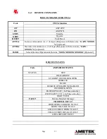
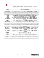
the zero attenuation command using the IBIC or WIBIC program, the command string
would look like this: "
ZA\r\n
". (The \r is National Instruments' notation for the carriage
return, and the \n is the line feed or 'new line' character.) Notice that the commands are
upper case only.
6.3 RS-232 INTERFACE
RS-232, a standard which defines the communication between DTE, data terminal equipment
to DCE, data communication equipment. The IFI Amplifiers have a RS-232, serial interface.
All amplifier functions can be controlled by coded messages sent over the interface bus via the
9-pin D-type socket connector on the rear panel of the unit.
1.3.1 RS-232 Wiring
Connect the serial port of the amplifier to a computer using a null modem cable or a standard
serial cable with a null modem adapter.
Pin #s Signal Name
Remote Terminal I/O
2
TXD
Output to remote terminal
3
RXD
Input from remote terminal
5
Signal GND
Signal reference
The RS-232 Serial Communication Settings:
Baud Rate:
9600 Baud.
Data Bits:
8
Parity:
None
Stop bits:
1
Flow control:
None
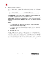
6.4
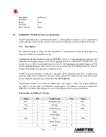
RS-422 / RS-485 INTERFACE
The IFI Amplifiers have the RS-422 and RS-485, serial interfaces. All amplifier functions can
be controlled by coded messages sent over the interface bus via the 9-pin D-type (RS-422) and
RJ-11 (RS-485), connector on the rear panel of the unit.
6.4.1 RS-422/RS-485 Wiring
Connect the RS-422/RS-485 port of the amplifier to a computer cable.
The RS-422/RS-485 Serial Communication Settings
:


