iET SRL Series Operation Manual Download Page 9

1

SRL Series

1

Introduction

Chapter 1 

INTRODUCTION

1.1  Introduction

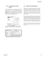
The  SRL  Series  (Figure  1.1)  are  extremely  stable, 
precise, laboratory or portable resistance standards.  
Their ruggedness and small size plus their virtually 
zero  temperature 

coeffi

  cient  makes  the  SRL  Series 

ideal for any applications outside of laboratory en-
vironment within the temperature range of 18°C to 
28°C.  The temperature chart provided with each unit 
enhances  the  accuracy  by  indicating  the  deviation 
from nominal for the operating temperature range in 
0.5°C increments.  Because of the low temperature 
coeffi

  cient, they require no oil-or-temperature bath.

The SRL series units are available in values ranging 
from 1 mΩ to 2 TΩ, with custom values available, 
to  satisfy  any  need.  They  are  built  with  precision 
resistors and use no adjustable resistors of any kind.

To  further  reduce  errors  caused  by  temperature 
changes, the SRL units are built with a temperature 
coeffi

  cient of near zero at 23°C. The binding posts 

are constructed of low-thermal emf material.

Figure 1-1:  SRL Series Resistance Standard

Summary of Contents for SRL Series

Page 1: ...ASUREMENT Email info ietlabs com TEL 516 334 5959 FAX 516 334 5988 www ietlabs com IET LABS INC SRL Series Resistance Standard Operation Manual Copyright 2022 IET Labs Inc Visit www ietlabs com for ma...

Page 2: ...PRECISION INSTRUMENTS FOR TEST AND MEASUREMENT Email info ietlabs com TEL 516 334 5959 FAX 516 334 5988 www ietlabs com IET LABS INC...

Page 3: ...t no charge when returned to IET Changes in this product not approved by IET or application of voltages or currents greater than those allowed by the speci cations shall void this warranty IET shall n...

Page 4: ...ctive 2002 96 EC This product complies with the WEEE Directive 2002 96 EC marking requirements The a xed label indicates that you must not discard this electrical electronic product in domestic househ...

Page 5: ...ions are taken Make all connections to the instrument before applying power Note the instrument s external markings described under Safety Symbols DO NOT Operate in an Explosive Atmosphere Do not oper...

Page 6: ...USED TAKE ALL MEASURES TO AVOID ACCIDENTAL CONTACT WITH ANY LIVE COMPONENTS USE MAXIMUM INSULATION AND MINIMIZE THE USE OF BARE CONDUCTORS WHEN USING THIS INSTRUMENT Use extreme caution when working w...

Page 7: ...ons for values 100 M 5 3 3 Thermal emf Considerations 5 3 4 Temperature Coe cient Constants 6 3 5 Environmental Conditions 6 3 5 1 Operating Temperature 6 3 5 2 Storage Temperature 6 3 6 Shipping and...

Page 8: ...lues 190 kW 4 Table 3 1 Connections for values 190 kW 4 Figure 3 2 Connections for values 1 MW and 100 MW 4 Table 3 2 Connections for values 1 MW and 100 MW 4 Figure 3 3 Connections for values 100 MW...

Page 9: ...s the accuracy by indicating the deviation from nominal for the operating temperature range in 0 5 C increments Because of the low temperature coe cient they require no oil or temperature bath The SRL...

Page 10: ...5 cm W x 12 7 cm D 3 4 x 4 15 x 5 Weight 0 73 kg 1 6 lb Figure 2 1 OPERATION GUIDE affixed to unit Figure 2 2 Temperature Calibration Chart JOS 19 Jun 2002 SRL 1 B2 9240246 N A 1 000 003 3 N A N A SRL...

Page 11: ...ppm 4 ppm 2 ppm tot 100 mW 200 mW 500 mW 4 bp s gnd 10 k SRL 10K 2 ppm 4 ppm 1 5 ppm tot 100 mW 200 mW 500 mW 4 bp s gnd 19 k SRL 19K 2 ppm 4 ppm 2 ppm tot 100 mW 200 mW 500 mW 4 bp s gnd 20 k SRL 20...

Page 12: ...esistance Change 18 C to 28 C 3 ppm Maximum Voltage 0 5 V Maximum Current 0 5 A LO HI LO HI SENSE CURRENT GND HI INPUT HI SENSE LO INPUT LO SENSE GROUND Binding Post Function CURRENT HI Current input...

Page 13: ...HI GROUND GUARD HI INPUT HI SENSE LO SENSE LO INPUT GROUND GUARD If no GUARD point exists on the measuring instrument it may be connected to GROUND 3 3 Thermal emf Considerations High quality gold pl...

Page 14: ...ult the Temperature Calibration Chart provided with each unit The calculated resistance value is provided be tween 18 C and 28 C in 0 5 C increments Figure 2 2 shows an example of this table 3 5 2 Sto...

Page 15: ...e device the following should be observed Calibration Interval General Considerations Required Equipment Calibration Procedure 4 3 1 Calibration Interval The recommended SRL Series calibration interva...

Page 16: ...precision high stability digi tal multimeter e g Fluke 8508A along with a set of resistance stan dards for ratio mode 4 3 4 Calibration Procedure To calibrate an SRL unit proceed as follows 1 Set up t...

Page 17: ......

Reviews: