background image

Print More Materials, All For Application

11

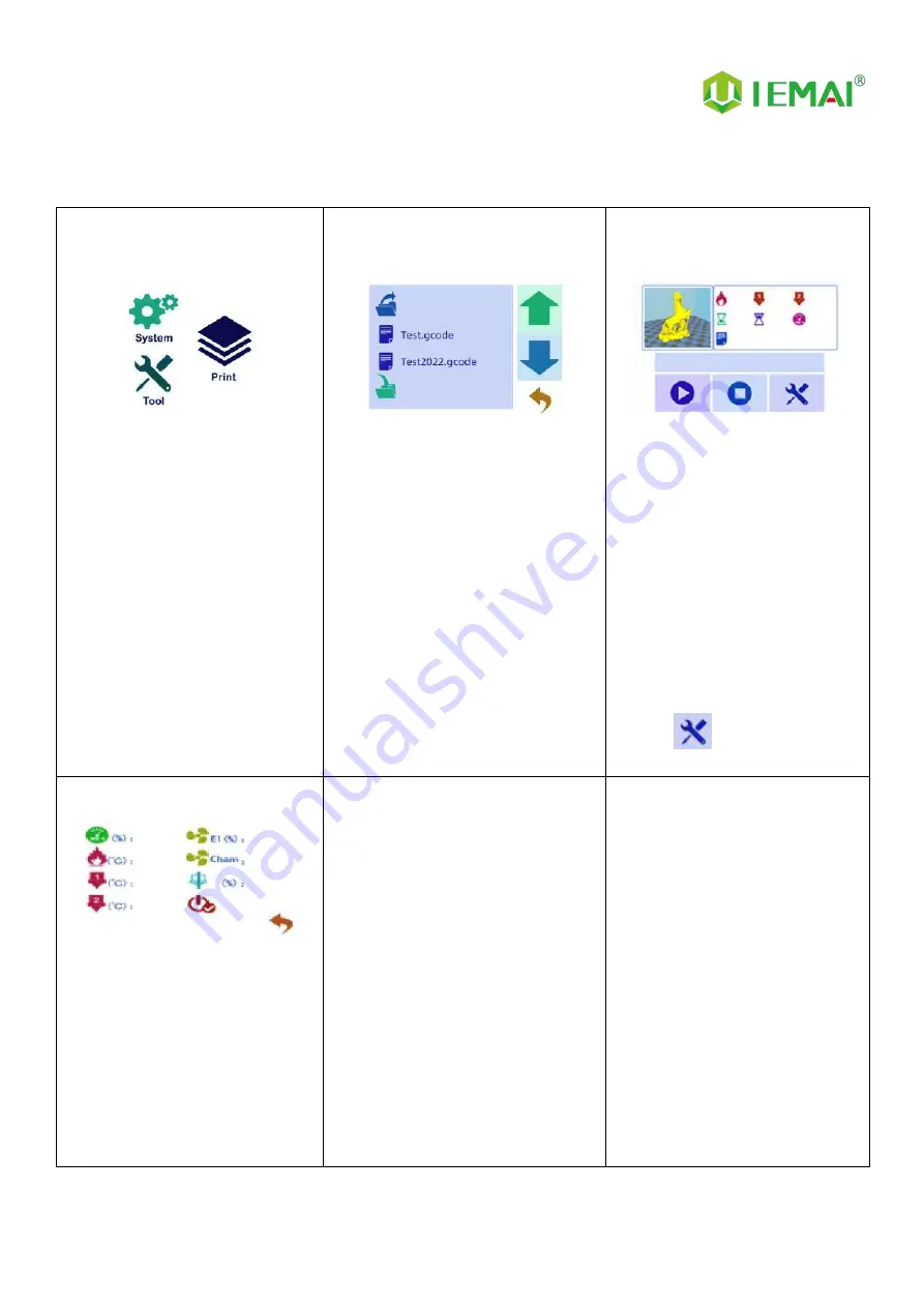
2.3.3 Print Interface

Figure 1: Main Interface

Click "Print" to go to Figure 2

Figure 2: File Interface

Check Specify G-code file to print or

delete the file

Figure 3: Print Interface

1. This interface is the main
interface in print You can view
thumbnails

2.Hot bed, Nozzle Temperature
and chamber temperature

3.Elapsed time, Time remaining 、
Current speed

4.File name, Print Progress Bar

4.You can control pause (resume)
and stop printing

5.Press "

" to reset during the

printing process

Figure 4:Print Setting Interface

1.This interface can be adjusted
during the printing process

2.Print Speed Ratio, Temperature of
Hot Bed, Nozzle

3.Fan Rate of E1/E2 and Chamber

4.Extrusion flow

5.Setting power off after printing

Summary of Contents for MAGIC-HT-PRO

Page 1: ...GIC HT PRO Operating Instructions www iemai3d com Please read this manual carefully before starting to operate This device is a Class A product Use in a general indoor environment may cause radio interference and therefore requires the user to take appropriate protective measures ...

Page 2: ...More Materials All For Application The contents of this operating instructions may be updated periodically Scan the QR code or visit the link below to get the latest version www iemai3d com index php download ...

Page 3: ...ilament Absent Warning 21 5 3 Temperature Setting of The Constant Temperature Chamber 22 5 4 Moisture Proof Cabinet Setting 23 5 5 PC based WIFI LAN control 24 6 Maintenance and Care 25 6 1 Maintenance of Linear Guide And Ball Screw 25 6 2 Adjustment of Belt Looseness 26 6 3 Dust Removal from Electrical Box Fans 27 6 4 Nozzle Maintenance 28 6 5 Equal Height Adjustment for Dual Print Heads 29 6 6 D...

Page 4: ...r high performance materials nylon PC ABS PETG ASA TPU and other engineering materials common material of the PLA class And composite reinforcement materials of the above materials carbon fiber glass fiber flame retardant ESD etc MAGIC HT PRO is equipped with a dual print head that lifts independently and support the printing of support materials including water soluble material PVA limonene solub...

Page 5: ...se the high quality filament provided by other regular filament manufacturers and users should be responsible for the loss caused by using low quality filament Please keep the consumables sealed and moisture proof if not in use for a long time please bake and dry them in advance before using them again Software Please use a 64 bit system with Windows 7 or above to run the software more than 4G of ...

Page 6: ...h The maximum temperature of the printing platform of this equipment can reach 200 C its heating is strictly prohibited to touch The maximum temperature of the chamber of this equipment can reach 120 C and it is strictly forbidden to touch it when it is heated Ensure that the power supply grounding terminal is well grounded to prevent the printer from not working properly or posing a risk of elect...

Page 7: ...Print More Materials All For Application 5 2 Detailed Parameter 2 1 Specification ...

Page 8: ...Print More Materials All For Application 6 ...

Page 9: ...Print More Materials All For Application 7 2 2 Device Layout ...

Page 10: ...Application 8 2 3 Interactive Interface The interactive Interface of this device adopts a 5 inch Color Touch Screen Resistive please read the following instructions carefully before first use Logic diagram of interactive interface ...

Page 11: ...original factory settings 5 Tap TPAAdjustment to correct the touch offset 6 Click WIFI to go to Figure 5 Figure 3 Info interface 1 This interface allows you to view the current coordinates of the XYZ axis 2 The current temperature of the left nozzle and right nozzle and hot bed Figure 4 About interface This interface allows you to view the name ID system version UI version and Power On Off sounds ...

Page 12: ...t information Figure 3 Manual Here can do the following 1 Select the moving unit of 0 1 10mm 2 Controls the XYZ axis for unit movement 3 Click to go back to the original point 4 Select E1 or E2 for unit extrusion Figure 4 Pre Heat interface 1 This interface allows you to set the preheat temperature of the hot bed left nozzle and Right nozzle Figure 5 Filament interface 1 Loading material 2 Unload ...

Page 13: ...You can view thumbnails 2 Hot bed Nozzle Temperature and chamber temperature 3 Elapsed time Time remaining Current speed 4 File name Print Progress Bar 4 You can control pause resume and stop printing 5 Press to reset during the printing process Figure 4 Print Setting Interface 1 This interface can be adjusted during the printing process 2 Print Speed Ratio Temperature of Hot Bed Nozzle 3 Fan Rate...

Page 14: ... device Step 3 1 Check The Door Glass Whether the Control Panel is Segmentation 2 Notice the starter kit and material package are placed under the platform 3 Please connect the power to start the equipment and then move up the platform to take out Step 4 1 Press the button below the door handle and the handle pops up to open the door panel If the machine is locked by a key the key is required to o...

Page 15: ... 1 The refrigerant can be viewed in the window behind the device Step 2 1 During shutdown the height of the normal refrigerant level should be located between 3 5 6 5 cm i e between the two red lines as shown in the figure If the level is not at the right position refer to the maintenance procedure for adding refrigerant ...

Page 16: ... normally as shown in figure Step 4 1 Control the E1 and E2 extrusion via the touch screen to see if the left and right nozzle gears rotate as shown in the figure Step 5 1 Through pre heat via the screen 2 The temperature can be set for the hot bed left nozzle and right nozzle 3 The temperature on the right represents the set temperature 4 The temperature on the left represents the actual temperat...

Page 17: ...ard to install it then align the snap position and push it inward Step 2 1 As shown in the picture for the platform of the nine positioning screws will build the platform positioning slot aligned with the positioning screws to push inward can be successfully installed Step 3 1 Find the platform glue in the kit and after the platform cools down apply three layers to the area to be printed horizonta...

Page 18: ...of the four corners of the platform please click the screen in the automatic leveling wait for the completion of the 49 points of height detection error and then print test Step 3 1 When printing the nozzle is found to be distant or close to the platform but the overall flatness of the platform has not changed that is the nozzle is equal to the height of the four corners of the platform please cli...

Page 19: ...t object respectively for the four corners of the platform to measure the height Step 5 1 When you can t push the nozzle manually 2 You can click unlock the motor 3 Push the nozzle to the four corners of the platform to measure the height Step 6 1 Leveling by the nuts under the four corners of the platform when the base height of the four corners is approximately the same 2 Automatic leveling can ...

Page 20: ...preheating temperature of different materials Step 2 1 Straighten the material Step 3 1 Cut the material to the tip Step 4 1 Load the material through the break test port 2 Manually feed it to the gears Step 5 1 Click to load materials 2 E1 for the left nozzle E2 for the right nozzle Step 6 1 Till the nozzle appears fine filament 2 Click Stop loading and unloading command ...

Page 21: ... gear 2 Manually ripping it out 3 And fix the threads 4 Do a good moisture preservation Step10 Recommended preheating nozzle temperature for commonly used materials Special Engineering Plastics PEEK 430 PEKK 430 PEI 1010 360 PEI 9085 360 PPSU 360 PPS 300 Reinforced Composites Material CF PEEK GF PEEK 450 CF PEKK ESD PEKK 430 GF PA CF PA 300 CF PC PC FR PC ABS 270 CF ABS 260 ESD PETG 260 CF PLA 220...

Page 22: ... the IEMAI slicing software Save the code to the SD card Please refer to the software tutorial for detailed slicing methods Step 2 1 Insert the SD card into the card slot on the right side of the device and select the file to be printed Step 3 1 Click ready to start printing ...

Page 23: ...axis of the printer has not moved after power failure otherwise it will not be able to continue printing after the last breakpoint 5 2 Filament Absent Warning Step 1 1 If the printer runs out of material during printing 2 Please select Yes in this screen to change the material Step 2 1 Unloading materials 2 Loading materials 3 E1 for left E2 for right 4 Unload the existing material first and then ...

Page 24: ...3 1 Through transposition keys increase decrease keys 2 Set target temperature 3 This is the left and right temperature setting at the same time 1 Press and hold the set button 2 When the target temperature window number stops jumping 3 Release the button 1 The left side of the number is the real time temperature 2 The right side numbers are the target temperature 3 The top is the left chamber tem...

Page 25: ... Target humidity value jump Step 3 1 Use the increase decrease keys 2 Set the specified target humidity 3 Recommended setting is a minimum of 10 RH Step 4 1 Click on the settings to return to the status display screen Step 5 1 Fan rotation indicates that the device is working Step 6 1 Status during long operation 2 The display will be in a sleep state 3 Can use start up display ...

Page 26: ...y the generated file to the SD card 2 and put it on the machine to print once Step 4 1 Copy the generated file to the SD card 2 and put it on the machine to print once 3 0 0 0 0 means not connected successfully Step 5 1 Enter the software and click Scan 2 Automatically reads machines in the network and connects them Step 6 1 Green status indicates successful connection Step 7 1 Preheat and movemen...

Page 27: ...Screw Ball screw and linear guide are the guarantee to keep secure operation and the correct maintenance can effectively increase the service life of the machine First step Use a towel or rag to remove the original lubricant from the linear guides and ball screws X and Y axes have a total of 6 guideways using the guideways cross structure Z axis direction has 2 guideways and 1 ball screw Second st...

Page 28: ... the top cover as shown in the figure all the screws at the top and both sides of the screws out and take off the top cover Step 2 Check the tightness of the belt by lightly pressing the belt with fingers The belt deformation is more than 2mm the belt needs to be tensioned when the upper belt is almost in contact with the lower belt Step 3 Loosen the two screws holding down the belt tighten the sc...

Page 29: ...nt of the motherboard and prevent the drive from overheating and out of step phenomenon Step two Removing the dust cover Insert the four corners of the dust cover from the dust cover to gently key out the dust cover Step Three Clear the dust on the dust cover and fan Use the air gun to remove the dust on the sponge inside the dust cover and blow clean the dust on the fan blow the fan pay attention...

Page 30: ...temperature nozzles need to be replaced as follows high temperature nozzles refer to peek use blockage treatment Step 1 remove the print head with reference to the disassembly and maintenance of the print head step two the heating block using a duckbill pliers clamp and use a 10mm socket to turn counterclockwise to remove the nozzle If you cannot turn the heating to 150 and then remove Step 3 take...

Page 31: ... 3 1 Move the nozzle to the left so that the right nozzle just above the position 2 where the left nozzle was previously tested 3 Place the auxiliary block between the nozzle and the platform 4 If the distance is not suitable proceed to the next step Step 4 1 Use a 1 5mm hexagon socket to loosen the top wire in the circle as shown 2 Make the nozzle and heating block throat can be moved up and down...

Page 32: ...ting Step 2 1 After setting the corresponding model size and other parameters 2 Enter the extrusion head 1 left nozzle parameter position Step 3 1 Find the TXT file with the name Start Code 1 in the random SD card Step 4 1 Copy the contents of the file and paste it into the start code box Step 5 1 Find the TXT file with the name Start Code 2 in the SD card Step 6 1 Copy the contents of the file an...

Page 33: ... to move to the positive direction of the Y axis decrease Y axis spacing negative Step 3 1 Open the slicing software 2 Adjust the parameters in the print head settings 3 Make up the difference according to the gap produced by printing 4 Difference between the right printhead and the left printhead Step 4 1 Print the two color miniature again 2 According to the printing effect to the left nozzle as...

Page 34: ...oosen the three screws as shown in the figure Step 3 Pull out the print head press the pneumatic interface black rubber to pull out the feed tube complete the removal To replace the print head proceed as follows Step 1 Install the print head in the original position tighten the front two screws so that the print head is closely connected to the base and then tighten the side screws Step 2 Check th...

Page 35: ...nscrew the six screws as shown to remove the side of the rear cover plate Step 2 Unscrew the nut by turning counterclockwise Step 3 Using a funnel for coolant addition Step 4 Make the coolant level is located between 3 5 6 5cm that is between two red lines screw on screw cap ...

Page 36: ...umables box through the small hole above When the desiccant appears orange it means the desiccant is relatively dry and gradually changes to green after absorbing water When the desiccant appears green open the desiccant box and put it inside the machine and bake it at 90 using the constant temperature chamber until the water of the desiccant evaporates and appears orange again then it can be used...

Page 37: ... cannot be moved and an alarm sound appears when you click to move Check if the limit switch is pressed Problem 3 Opposite direction of motion Open the firmware and change the control code 1 or 1 7 2 Temperature Problem Solution Problem one click on the heating the temperature does not change a few seconds later prompted the heating power is insufficient check the heating head temperature rise Att...

Page 38: ...e platform is able to print that material adjust the platform and nozzle gap when the zero point is small see Printing Installing the Build Platform and Leveling for more information Problem 3 Dual head printing does not work well together According to the maintenance nozzle spacing adjustment spacing Problem 4 Use of automatic unload filament but stuck between extrusion gear and extrusion clamp R...

Page 39: ... which causes the material to expand and jam the filaments Problem 2 After printing for a period of time some black material is extruded and no longer comes out of the silk Treatment I Use the nozzle corresponding size of the needle to unclog the nozzle and extrude again will be internal Treatment II Step 1 Refer to the print head disassembly and maintenance after removing the print head Step 2 Us...

Page 40: ... 38 8 Appendix Appendix A The difference between high and low temperature of the print head External differentiation can be seen nozzle style hexagonal nut style for high temperature nozzles into a cone type for the general temperature nozzle ...

Page 41: ...ber board put into the machine heating hot bed 80 baking 3 minutes so that the water in the glue evaporated to reach the maximum paste strength 3 After using for a long time when the residual glue on the platform is too much you can take off the carbon fiber board and rinse it with clean water and re glue it Attention It is recommended to use the side skirt attachment type for printing model with ...

Page 42: ...gure 2 The skirt lines are connected and fused into one plane This means that the distance between the nozzle and the platform is more appropriate and such a skirt effectively increases the contact surface between the model and the platform increasing the adhesion force Attention If the nozzle is too close to the platform there is no gap between the platform and the nozzle it will lead to nozzle e...

Reviews: