background image

10

K

ARA

T

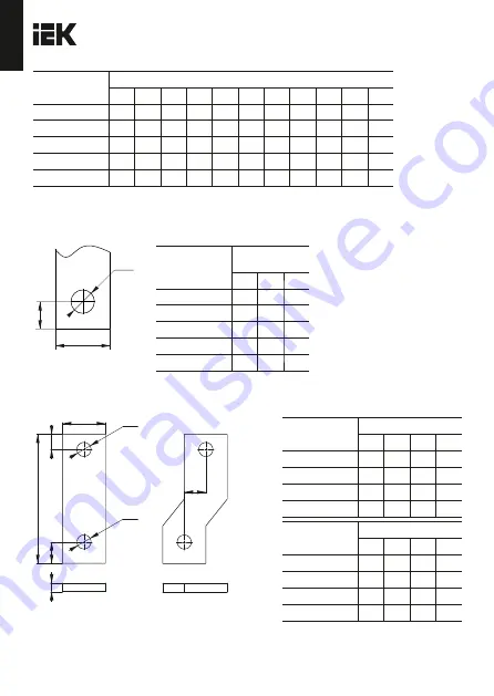
Ðèñóíîê

 2 – 

Ðàçìåðû


øèíû


äëÿ


âûêëþ÷àòåëÿ

 / Figure 2 – Busbar dimensions for the switch

A

B

Ж

D

Òèïîèñïîëíåíèå / 
Type

Ðàçìåðû / 
Dimensions, mm
À

Â

D

ÂÀ88-31

17,5

7,5

8,5

ÂÀ88-32

17,5

8,0

8,5

ÂÀ88-35

23,5

12,0 8,5

ÂÀ88-37

32,5

13,0 10,5

ÂÀ88-40

44,5

15,0 10,5

Òèïîèñïîëíåíèå / 
Type

Ðàçìåðû / Dimensions, mm

L

L1

L2

L3

W

W1

W2

W3

H

H1

Ж

d

ÂÀ88-31

165

235

121

117

78

25

18

25

87

62

4,5

ÂÀ88-32 

151

253

132

129

93

30

18

30

99

64

4,5

ÂÀ88-35 

165

300

146

125

107

35

24

35

98

69

4,5

ÂÀ88-37 

257

465

224

194

150

48

33

44

150

99

8

ÂÀ88-40 

281

496

243

243

210

70

45

70

155

103

7

Ðèñóíîê

 1 


Ãàáàðèòíûå


è


óñòàíîâî÷íûå


ðàçìåðû


âûêëþ÷àòåëÿ

 / Figure 1 

 Overall and mounting 

dimensions of circuit breakers

 b 

 a 

 L


Ж

D1 

Ж

D2 

 W 

 H 

 c 

a

) Äëÿ öåíòðàëüíîãî 

âûâîäà / For central output

á) Äëÿ áîêîâûõ âûâîäîâ / 
For side leads

Ðèñóíîê

 3 – 

Ðàçìåðû


ðàñøèðåííûõ


âûâîäîâ


è


ïåðåõîäíèêîâ


äëÿ


âûêëþ÷àòåëÿ

 / 

Figure 3 – Dimensions of the extended terminals and adapters for the switch


Òèïîèñïîëíåíèå / 
Type

Ðàçìåðû / Dimensions, mm

W

H

L

D1

ÂÀ88-32 (125)

16

4

50

8,5

ÂÀ88-35 (250)

20

5

67

9,0

ÂÀ88-37 (400)

28

8

70

10,0

ÂÀ88-40 (800)

40

8

120

13,0

Òèïîèñïîëíåíèå / 
Type

Ðàçìåðû / Dimensions, mm

D2

c

a

b

ÂÀ88-32 (125)

8,5

8

8

8

ÂÀ88-35 (250)

9,0

10

10

12

ÂÀ88-37 (400)

14,0

14

11

15

ÂÀ88-40 (800)

13,0 10

14

20

Summary of Contents for BA88-31

Page 1: ...17516 1 IEC 60947 2 50 40 90 20 IP30 14254 IEC 60529 IP00 2000 5000 1 004 2011 037 2016 IEC 60947 2 IEC 60947 7 3 3 15150 40 60 88 MASTER IEK 30 690 50 IEC 60947 1 A B 3 IEC 60947 1 1 88 MASTER RU KAR...

Page 2: ...2 10 IR 3 4 1 20 2 5 2 7 88 3 5 1 5 6 40 C 2 4 6 5 6 7 6 7 9 13983 KARAT...

Page 3: ...3 10434 17441 1 3 5 1 3 5 90 1 3 5 2 4 6 23216 4 2 15150 8 10 40 C 60 C KARAT...

Page 4: ...aker can be operated under the following conditions operating temperature range from minus 40 to plus 60 environment condition group according to IEC 60947 1 A B utilization category according to IEC...

Page 5: ...uit diagram of the circuit breaker is shown in figure 6 The circuit breaker is installed on a metal panel with a thickness of at least 1 5 mm or an insulating panel with a thickness of at least 6 mm a...

Page 6: ...fer to a specialized recycling company Basic insulation is a precautionary measure for basic protection against electric shock and no protection against damage is provided Transportation of the circui...

Page 7: ...arameter denomination Value Base altitude m 2000 3000 4000 5000 Correction factor of operating current 1 0 94 0 88 0 83 Table 2 Parameter denomination Value for circuit breaker of following type 88 31...

Page 8: ...8 8 8 10 10 Weight kg maximum 0 78 1 4 1 71 5 48 9 9 Continuation of table 2 Table 3 Test current Tripping or non tripping time depending on the setting of thermal releases Requited result I 63 R I 63...

Page 9: ...nductors set 1 1 1 1 1 Fasteners for mounting on a mounting plate set 1 1 1 1 1 Denomination 88 31 88 32 88 35 88 37 88 40 Mounting plate of plug in type 1 125 1 250 1 400 630 1 630 800 Mechanical int...

Page 10: ...7 35 24 35 98 69 4 5 88 37 257 465 224 194 150 48 33 44 150 99 8 88 40 281 496 243 243 210 70 45 70 155 103 7 1 Figure 1 Overall and mounting dimensions of circuit breakers b a L D1 D2 W H c a For cen...

Page 11: ...the rated current on the ambient temperature Rated current Environmental temperature C 0 25 0 25 32 125 88 31 88 32 88 35 Rated current Environmental temperature C Rated current Environmental temperat...

Page 12: ...ng time sec 88 35 Time current characteristics of A88 35 circuit breakers Operating time sec 88 37 Time current characteristics of A88 37 circuit breakers Operating time sec 88 40 ime current characte...

Page 13: ...agnetic release B C H H H 1 3 2 1 Non insulated connection 2 Insulated cable 3 Cable lugs D KARAT Minimum distance between the centers of two horizontally mounted switches Minimum distance of installa...

Page 14: ...ion in a metal grounded shield Installation in an isolated shield mm D mm mm mm mm mm mm mm 88 31 25 20 20 25 10 20 100 110 88 32 35 20 35 25 10 20 100 110 88 35 45 25 45 35 10 25 160 120 88 37 45 25...

Reviews: