


RACK-360 QIG IEI Integration Corp. Page 8
1
Power switch cable
Table 4: Chassis Connectors
The pin definitions for the USB cable are shown below.
PIN No.
Description
Color
1
+5V
Red
2
D-
Dark Yellow
3
D+
Yellow
4
GND
Brown
Table 5: Pin Definitions of USB Cable
STEP 10: PSU CABLE AND INTERFACE
CABLE CONNECTIONS
Before you reinstall the hold-down clamp and the cover, the following
cables need to be connected.
Step 1:
PSU cables from the PSU to the full-size CPU card,
drives and the cooling fan must be connected.
Step 2:
The drive interface connectors must be connected to the
CPU card.
Step 0:
STEP 11: HOLD-DOWN CLAMP AND
COVER REINSTALLATION
After you have completed the above procedures, the hold-down
clamp and cover can be reinstalled. To do this, align the screw holes
on both ends of the hold-down clamp with the screw holes on both
sides of the chassis and reinsert the four previously removed
retention screws. After that, slide the cover back over the chassis and
reinsert the six previously removed retention screws.
CHASSIS MAINTENANCE
F
AN
R
EPLACEMENT
NOTE:
Please ensure that the power of the computer is switched off before
you replace a fan.
There is one 12 cm cooling fan inside the RACK-360 chassis. To
replace a fan, please follow the steps below.
Step 1:
Remove the chassis cover. (Refer to Step 3: Top Cover
and Hold-down Clamp Removal)
Step 2:
Unplug the power cable that is connected to the fan.
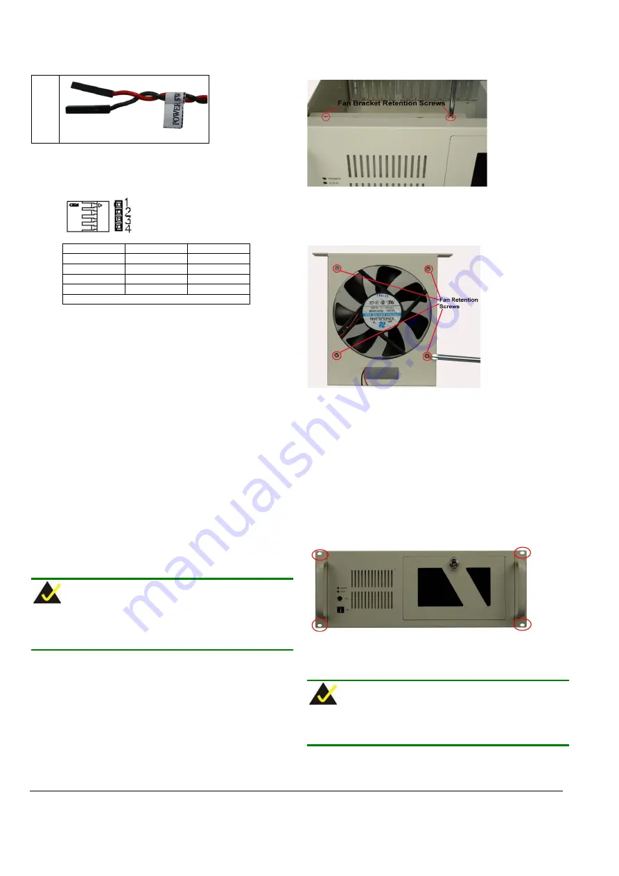
Step 3:
Remove the two retention screws at the top of the fan
bracket.
Figure 17: Remove the Fan Bracket
Step 4:
Pull the fan bracket out of the chassis and remove the
four retention screws on each corner of the fan.
Figure 18: Remove the Fan Retention Screws
Step 5:
Replace the fan and secure the new fan to the bracket
with four retention screws.
Step 6:
Slide the bracket back into the chassis and secure it to
the chassis with the four previously removed retention
screws.
Step 0:
C
ABINET
I
NSTALLATION
Supporting rails, rack trays, or slide rails can be implemented using
the mounting holes on the sides of the chassis. The four mounting
holes in the two handles on the sides of the chassis are shown below.
Figure 19: Locations of the Four Mounting Holes
NOTE:
If the system is running critical applications, please find the appropriate
time to backup data and properly shut down the system.