PPC-F06B-BT Panel PC
Page 18
3.7 mSATA Module Installation
The PCIe Mini card slot on the motherboard of the PPC-F06B-BT supports mSATA
module. To install an mSATA module, please follow the steps below.
Step 1:
Remove the back cover. See Section
Step 2:
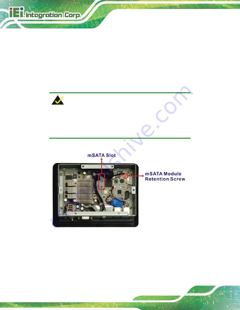
Locate the full-size PCIe Mini card slot. Remove the preinstalled retention screw
on the screw pillar of the PCIe Mini card slot as shown in
NOTE:
In the model with wireless LAN function, this PCIe Mini slot is reserved
for wireless LAN module installation. If the slot is installed with a
wireless LAN module, please install a SATA DOM for system storage.
Figure 3-4:
mSATA Module Slot Location
Step 3:
Line up the notch on the mSATA module with the notch on the connector. Slide
the PCIe Mini card into the socket at an angle of about 20º.
Summary of Contents for PPC-F06B-BT
Page 13: ...PPC F06B BT Panel PC Page 1 1 Introduction Chapter 1 ...
Page 18: ...PPC F06B BT Panel PC Page 6 1 7 Dimensions Figure 1 6 PPC F06B BT Dimensions mm ...
Page 21: ...PPC F06B BT Panel PC Page 9 2 Unpacking Chapter 2 ...
Page 25: ...PPC F06B BT Panel PC Page 13 3 Installation Chapter 3 ...
Page 52: ...PPC F06B BT Panel PC Page 40 4 BIOS Setup Chapter 4 ...
Page 80: ...PPC F06B BT Panel PC Page 68 5 Interface Connectors Chapter 5 ...
Page 92: ...PPC F06B BT Panel PC Page 80 Appendix A A Regulatory Compliance ...
Page 98: ...PPC F06B BT Panel PC Page 86 B BIOS Configuration Options Appendix B ...
Page 101: ...PPC F06B BT Panel PC Page 89 C Safety Precautions Appendix C ...
Page 107: ...PPC F06B BT Panel PC Page 95 D Watchdog Timer Appendix D ...
Page 110: ...PPC F06B BT Panel PC Page 98 Appendix E E Hazardous Materials Disclosure ...


