PPC-F06B-BT Panel PC
Page 26
3.10 AT/ATX Mode Selection
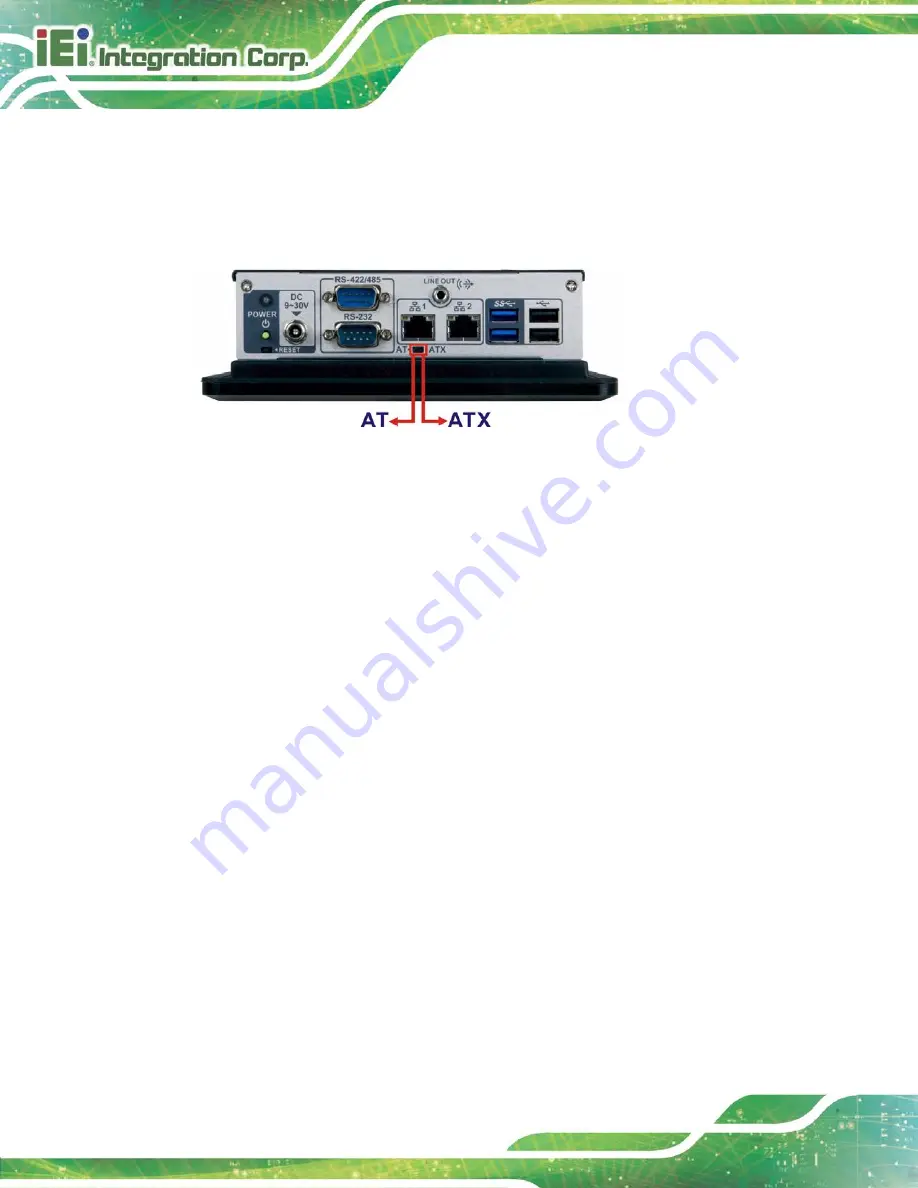
AT and ATX power modes can both be used on the PPC-F06B-BT panel PC. The
selection is made through an AT/ATX switch on the I/O interface panel. The switch is
shown below.
Figure 3-16: AT/ATX Mode Selection
3.10.1 AT Power Mode
With the AT mode selected, the power is controlled by a central power unit rather than a
power switch. The PPC-F06B-BT panel PC turns on automatically when the power is
connected. The AT mode benefits a production line to control multiple panel PCs from a
central management center and other applications including:
ATM
Self-service kiosk
Plant environment monitoring system
Factory automation platform
Manufacturing shop flow
3.10.2 ATX Power Mode
With the ATX mode selected, the PPC-F06B-BT panel PC goes in a standby mode when it
is turned off. The panel PC can be easily turned on via network or a power switch in
standby mode. Remote power control is perfect for advertising applications since the
broadcasting time for each panel PC can be set individually and controlled remotely. Other
possible application includes
Security surveillance
Point-of-Sale (POS)
Summary of Contents for PPC-F06B-BT
Page 13: ...PPC F06B BT Panel PC Page 1 1 Introduction Chapter 1 ...
Page 18: ...PPC F06B BT Panel PC Page 6 1 7 Dimensions Figure 1 6 PPC F06B BT Dimensions mm ...
Page 21: ...PPC F06B BT Panel PC Page 9 2 Unpacking Chapter 2 ...
Page 25: ...PPC F06B BT Panel PC Page 13 3 Installation Chapter 3 ...
Page 52: ...PPC F06B BT Panel PC Page 40 4 BIOS Setup Chapter 4 ...
Page 80: ...PPC F06B BT Panel PC Page 68 5 Interface Connectors Chapter 5 ...
Page 92: ...PPC F06B BT Panel PC Page 80 Appendix A A Regulatory Compliance ...
Page 98: ...PPC F06B BT Panel PC Page 86 B BIOS Configuration Options Appendix B ...
Page 101: ...PPC F06B BT Panel PC Page 89 C Safety Precautions Appendix C ...
Page 107: ...PPC F06B BT Panel PC Page 95 D Watchdog Timer Appendix D ...
Page 110: ...PPC F06B BT Panel PC Page 98 Appendix E E Hazardous Materials Disclosure ...


