PCIE-Q370 Full-size PICMG 1.3 CPU Card
Page 119
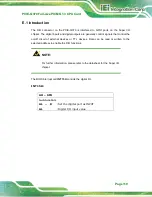
E.1 Introduction
The DIO connector on the PCIE-Q370 is interfaced to GPIO ports on the Super I/O
chipset. The digital inputs and digital outputs are generally control signals that control the
on/off circuit of external devices or TTL devices. Data can be read or written to the
selected address to enable the DIO functions.
NOTE:
For further information, please refer to the datasheet for the Super I/O
chipset.
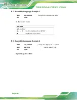
The BIOS interrupt call
INT 15H
controls the digital I/O.
INT 15H:
AH – 6FH
Sub-function:
AL – 8
:Set the digital port as INPUT
AL
:Digital I/O input value
Summary of Contents for PCIE-Q370
Page 15: ...PCIE Q370 Full size PICMG 1 3 CPU Card Page 1 Chapter 1 1 Introduction ...
Page 24: ...PCIE Q370 Full size PICMG 1 3 CPU Card Page 10 Chapter 2 2 Packing List ...
Page 29: ...PCIE Q370 Full size PICMG 1 3 CPU Card Page 15 Chapter 3 3 Connectors ...
Page 58: ...PCIE Q370 Full size PICMG 1 3 CPU Card Page 44 Chapter 4 4 Installation ...
Page 76: ...PCIE Q370 Full size PICMG 1 3 CPU Card Page 62 Chapter 5 5 BIOS ...
Page 120: ...PCIE Q370 Full size PICMG 1 3 CPU Card Page 106 Appendix A A Regulatory Compliance ...
Page 122: ...PCIE Q370 Full size PICMG 1 3 CPU Card Page 108 B Product Disposal Appendix B ...
Page 124: ...PCIE Q370 Full size PICMG 1 3 CPU Card Page 110 Appendix C C BIOS Options ...
Page 127: ...PCIE Q370 Full size PICMG 1 3 CPU Card Page 113 ...
Page 128: ...PCIE Q370 Full size PICMG 1 3 CPU Card Page 114 Appendix D D Terminology ...
Page 132: ...PCIE Q370 Full size PICMG 1 3 CPU Card Page 118 Appendix E E Digital I O Interface ...
Page 135: ...PCIE Q370 Full size PICMG 1 3 CPU Card Page 121 Appendix F F Watchdog Timer ...
Page 138: ...PCIE Q370 Full size PICMG 1 3 CPU Card Page 124 Appendix G G Hazardous Materials Disclosure ...


