PAC-125G QIG IEI Technology Corp. Page 5
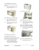
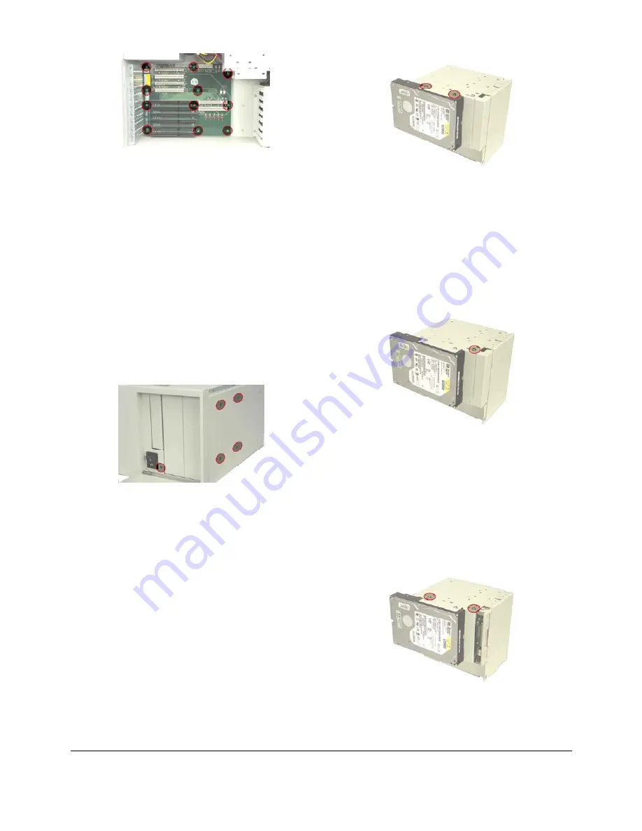
Figure 8: Backplane Retention Screws
STEP 5: DISK DRIVE INSTALLATION
The PAC-125G chassis has the capacity for two 5.25”
Optical drives, one 3.5” front accessible drive (FDD or HDD)
and one 3.5” internal HDD.
To install the drives please follow the steps outlined in the
sections below.
S
TEP
5.1:
D
RIVE
B
RACKET
R
EMOVAL
To remove the drive bracket, please follow the steps below:
Step 1:
Open the front panel cover.
Step 2:
Remove the five drive bracket retention screws,
four from the right side of the chassis and one
from the front panel.
Figure 9: Drive Bracket Retention Screws
Step 3:
Slide the drive bracket backwards and lift the
drive bracket up gently.
S
TEP
5.2:
3.5
"
I
NTERNAL
HDD
I
NSTALLATION
To install a 3.5” HDD into the drive bracket, please follow
the steps below:
Step 1:
Mount a 3.5” HDD onto the drive bracket. Make
sure the HDD PCB board is against the left side
of the drive bracket, and the power connector and
IDE/SATA connector are at the rear of the drive
bracket.
Step 2:
Align the retention screw holes in the 3.5” HDD
with the retention screw holes in the 3.5” internal
HDD drive bay.
Step 3:
To secure the HDD to the drive bracket, insert
four retention screws, two from each side of the
HDD.
Step 0:
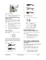
Figure 10: 3.5
"
Internal HDD Retention Screws
S
TEP
5.3:
3.5
"
F
RONT
A
CCESSIBLE
FDD/HDD
I
NSTALLATION
To install a 3.5” drive (FDD or HDD) into the drive bracket,
please follow the steps below:
Step 1:
Remove the 3.5” drive bay front cover by
removing the two front cover retention screws,
one from each side of the front cover.
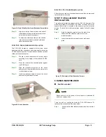
Figure 11: 3.5
"
Drive Bay Front Cover Retention Screws
Step 2:
Slide a 3.5” drive (FDD or HDD) into the 3.5”
drive bay.
Step 3:
Align the retention screw holes in the 3.5” drive
(FDD or HDD) with the retention screw holes in
the 3.5” drive bay.
Step 4:
To secure the 3.5” drive (FDD or HDD) to the 3.5”
drive bay, insert four retention screws, two on
each side of the 3.5” drive (FDD or HDD).
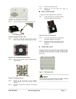
Figure 12: FDD Retention Screws


