PPC-F08B/F10B-BT Panel PC
Page 26
Step 7:
Remove the nut and washer from the SMA connector
at the other end of the RF
cable.
Step 8:
Insert the SMA connector to the antenna connector holes on the top panel.
Step 9:
Secure the SMA connector by inserting the washer and tightening it with nut.
Step 10:
Install the external antenna.
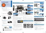
Figure 3-13: Securing SMA Connector and External Antenna Installation
3.9 Serial Port Configuration and Connection
The PPC-F08B/F10B-BT series has two serial ports, including one RS-232/422/484 port
and one RS-232 port. The port locations are shown in
. The jumper settings
and pinouts of the serial ports are listed in the following sections.
Figure 3-14: PPC-F10B-BT Serial Port Locations
Summary of Contents for F10B-BT
Page 14: ......
Page 15: ...PPC F08B F10B BT Panel PC Page 1 1 Introduction Chapter 1...
Page 25: ...PPC F08B F10B BT Panel PC Page 11 2 Unpacking Chapter 2...
Page 30: ...PPC F08B F10B BT Panel PC Page 16 3 Installation Chapter 3...
Page 60: ...PPC F08B F10B BT Panel PC Page 46 Chapter 4 4 System Maintenance...
Page 64: ...PPC F08B F10B BT Panel PC Page 50 5 BIOS Setup Chapter 5...
Page 97: ...PPC F08B F10B BT Panel PC Page 83 6 Interface Connectors Chapter 6...
Page 112: ...PPC F08B F10B BT Panel PC Page 98 Appendix A A Regulatory Compliance...
Page 118: ...PPC F08B F10B BT Panel PC Page 104 B BIOS Configuration Options Appendix B...
Page 121: ...PPC F08B F10B BT Panel PC Page 107 C Safety Precautions Appendix C...
Page 127: ...PPC F08B F10B BT Panel PC Page 113 D Watchdog Timer Appendix D...
Page 130: ...PPC F08B F10B BT Panel PC Page 116 Appendix E E Hazardous Materials Disclosure...


