IEI Technology DM-150GS/R-R30 User Manual Download Page 22


DM  S e rie s   Mo n ito r 

P a g e   12 


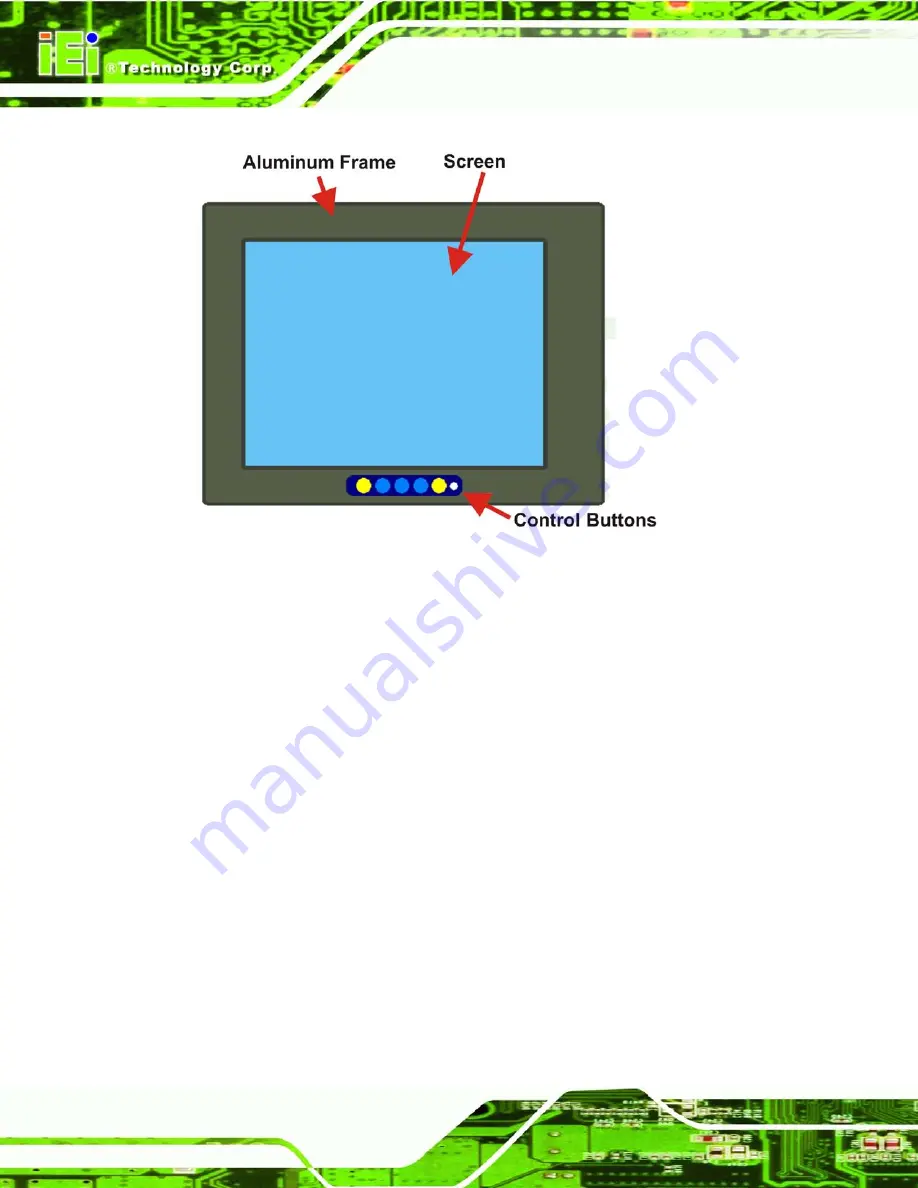
Figure 2-2: Front Panel Variant 2 


2.2.4


Bo tto m   P a n e l 

All peripheral device connectors  are located on the bottom panel of the DM series LCD 

monitor. The following sections describe  the bottom panel variants and their associated 

connectors. 

2.2.5


Ava ila b le   Co n n e c to rs  

There are a number of bottom panel peripheral device connectors  available for the DM 

series LCD monitor. 


VGA connector 


DVI-D connector 


12V power connector 


9~36V terminal block  (Optional for M model, refer to 

Table 1-1


RS-232 serial connector 


USB connector 

Summary of Contents for DM-150GS/R-R30

Page 1: ...DM Series Monitor Page I IEI Technology Corp Us er Manual DM Series Industrial Monitor MODEL DM Series 15 19 LCD Monitor VGA DVI D IP 65 Protection RoHS Rev 3 00 7 J une 2013...

Page 2: ...DM Series Monitor Page II Revis ion Date Version Changes 7 June 2013 3 00 Initial Release...

Page 3: ...rising out of the use or inability to use the product or documentation even if advised of the possibility of such damages This document contains proprietary information protected by copyright All righ...

Page 4: ...INTRODUCTION 10 2 2 FRONT PANEL 10 2 2 1 Front Panel Variants 10 2 2 2 Front Panel Variant 1 10 2 2 3 Front Panel Variant 2 11 2 2 4 Bottom Panel 12 2 2 5 Available Connectors 12 2 3 PHYSICAL DIMENSIO...

Page 5: ...ckaging 28 5 2 2 Unpacking Procedure 28 5 2 3 Packing List 29 5 3 PRE INSTALLATION PREPARATION 29 5 3 1 Tools 29 5 3 2 Voltage Select Jumper Settings 30 5 4 CONNECTORS 31 5 4 1 Rear Panel Connectors O...

Page 6: ...OUCH SCREEN 55 7 3 TOUCH PANEL DRIVER INSTALLATION 56 7 4 CHANGE THE TOUCH SCREEN INTERFACE 59 7 5 CALIBRATING THE TOUCH SCREEN 59 8 GASKET REPLACEMENT 62 8 1 GASKET REPLACEMENT 63 A SAFETY PRECAUTION...

Page 7: ...4 2 EDID Page 78 C 4 3 Image Page 79 C 4 4 Display Page for analog signal 80 C 4 5 Color Page 81 C 4 6 PIP Page 82 C 4 7 System Page 83 C 4 8 About Page 84 C 5 SMARTOSD FAQ 85 C 5 1 Windows 2000 Insta...

Page 8: ...Connector 33 Figure 5 4 12V Power Connector 33 Figure 5 5 RS 232 Touch Panel Connector 34 Figure 5 6 USB Touch Panel Connector 34 Figure 5 7 Terminal Block 35 Figure 5 8 DM 150 Panel Opening Unit mm 3...

Page 9: ...7 PenMount Monitor Icon 60 Figure 7 8 PenMount Monitor Popup Menu 60 Figure 7 9 Configuration Screen 60 Figure 7 10 Calibration Initiation Screen 61 Figure 7 11 Calibration Screen 61 Figure 8 1 Gaske...

Page 10: ...DM 150 LCD Specifications 20 Table 3 2 DM 170 LCD Specifications 21 Table 3 3 DM 190 LCD Specifications 22 Table 4 1 AV 6600 Peripheral Interface Connectors 25 Table 4 2 AV 6600 Rear Panel Connectors...

Page 11: ...DM Series Monitor Page 1 Chapter 1 1 Introduction...

Page 12: ...on which effectively wards off dust and water Flexible analog or digital interfaces are provided for ease of connection with a management computer 1 2 Features The DM series have the following standar...

Page 13: ...R R30 Yes DM 190GS R R30 19 DM 190GMS R R30 Yes Table 1 1 DM Series Model Variations 1 4 Applications The DM series LCD monitor is designed for rigorous industrial environments where it may be exposed...

Page 14: ...ces that can be used in harsh industrial environments The following sections describe the physical layout of the DM series LCD monitors 1 5 1 Front View The front of the DM series LCD monitor is a fla...

Page 15: ...tor Page 5 Figure 1 2 Typical Monitor Front View 1 5 2 Bottom Panel View Figure 1 3 shows the bottom panel of the DM series LCD monitor All connectors are fully described in Section 5 4 Figure 1 3 Bot...

Page 16: ...y of control interfaces receiving and managing signals from a CPU card through cabling Figure 1 4 shows the AV 6600 AD board as a sample of a typical AD board for the DM series LCD monitor Refer to Ch...

Page 17: ...erface Resistive 5 wire USB RS 232 interface Resistive 5 wire USB RS 232 interface Resistive 5 wire USB RS 232 interface Resistive 5 wire USB RS 232 interface AD Board AV 6600 Aluminum AV 6600 AV 6600...

Page 18: ...nternal Prescan EMC Class A Internal Prescan EMC Class A Internal Prescan EMC Class A Internal Prescan EMC Class A Internal Prescan EMC Class A Table 1 2 DM Series Specifications 1 7 Certifications Al...

Page 19: ...DM Series Monitor Page 9 Chapter 2 2 Mechanical Overview...

Page 20: ...Panel Variants Table 2 1 shows the three front panel variants for the DM series LCD monitor Model OSD Control Panel Location Variant Number DM 150 DM 170 Vertically along the right side of the aluminu...

Page 21: ...ariant 1 2 2 3 Front Panel Variant 2 The following model of the DM series LCD monitor has an OSD control panel located horizontally along the bottom of the aluminum frame DM 190 Figure 2 2 shows the l...

Page 22: ...The following sections describe the bottom panel variants and their associated connectors 2 2 5 Available Connectors There are a number of bottom panel peripheral device connectors available for the...

Page 23: ...ensions for each model of the DM series LCD monitor 2 3 1 General Phys ical Dimens ions General physical dimensions for the DM series LCD monitors are shown in Table 2 2 Model Width mm Height mm Depth...

Page 24: ...DM Series Monitor Page 14 2 3 2 DM 150 Phys ical Dimens ions The physical dimensions of the DM 150 are shown in Figure 2 3 Figure 2 3 DM 150 Physical Dimensions millimeters...

Page 25: ...DM Series Monitor Page 15 2 3 3 DM 170 Phys ical Dimens ions The physical dimensions of the DM 170 are shown in Figure 2 4 Figure 2 4 DM 170 Physical Dimensions millimeters...

Page 26: ...DM Series Monitor Page 16 2 3 4 DM 190 Phys ical Dimens ions The physical dimensions of the DM 190 are shown in Figure 2 5 Figure 2 5 DM 190 Physical Dimensions millimeters...

Page 27: ...nting If the VESA mounting kit is purchased separately please make sure the mounting kit is UL listed 2 3 6 DM 150 Mounting Kits Table 2 3 lists the mounting kits available for the DM 150 monitor Mode...

Page 28: ...ting Kits 2 3 8 DM 190 Mounting Kits Table 2 5 lists the mounting kits available for the DM 190 monitor Model DM 190 Panel Mounting Kit PK 190M Rack Mounting Kit RK 190MS R10 Wall Mounting Kit WK 190M...

Page 29: ...DM Series Monitor Page 19 Chapter 3 3 LCD Specifications...

Page 30: ...ons 3 1 2 DM 150 LCD Specifications Table 3 1 lists the DM 150 LCD specifications Items DM 150 Size 15 Brand AUO Model G150XG01 V3 Backlight LED Brightness cd m2 400 Resolution 1024 x 768 Screen Scale...

Page 31: ...n Scale 4 3 Life Time 50000H Contrast Ratio 800 1 View Angle H V 170 160 Interface 2ch LVDS Operating Temperature 30 85 C Active Area mm 337 9 x 270 3 Pixel Pitch mm 0 264 Display Mode Normal White Nu...

Page 32: ...Scale 4 3 Life Time 50000H Contrast Ratio 1000 1 View Angle H V 170 160 Interface 2ch LVDS Operating Temperature 0 50 C Active Area mm 376 32 x 301 06 Pixel Pitch mm 0 294 Display Mode Normal White N...

Page 33: ...DM Series Monitor Page 23 Chapter 4 4 AD Board...

Page 34: ...ibe each AD board in detail 4 2 AV 6600 AD Board Overview The AV 6600 AD board provides a wide variety of control interfaces receiving and managing interface signals from a CPU card through cabling Th...

Page 35: ...tor CN5 Power output connector 12 V 2 pin wafer connector CN3 Power output connector 5 V 2 pin wafer connector CN4 Power input connector 3 pin connector CN2 RS 232 and USB signal input connector 12 pi...

Page 36: ...DM Series Monitor Page 26 Chapter 5 5 Ins tallation...

Page 37: ...Since the monitor may weigh up to 10 kg not including a swing arm or other accessories please ensure at least two people assist with mounting the monitor Air Circulation Make sure there is sufficient...

Page 38: ...w WARNING The front side LCD screen has a protective plastic cover stuck to the screen Only remove the plastic cover after the DM series LCD monitor has been properly installed This ensures the screen...

Page 39: ...erminal block Optional for M model If any of these items are missing or damaged contact the distributor or sales representative immediately 5 3 Pre ins tallation Preparation 5 3 1 Tools Before install...

Page 40: ...configured for a 12V power source Do not change the jumper setting unless a 9 36V DC power connector is present on the rear panel and is to be used as the monitor s power source To properly set the vo...

Page 41: ...s DM 150 DM 170 DM 190 VGA Yes Yes Yes DVI D Yes Yes Yes Power 12V J ack Yes Yes Yes RS 232 for Touch Panel Yes Yes Yes USB for Touch Panel Yes Yes Yes Power 9 36V Terminal Block Optional for M model...

Page 42: ...UND 11 NC 2 GREEN 7 GROUND 12 DDCDAT 3 BLUE 8 GROUND 13 HSYNC 4 NC 9 NC 14 VSYNC 5 GROUND 10 GROUND 15 DDCCLK Table 5 2 VGA Connector Pinouts Figure 5 2 VGA Connector 5 4 3 DVI D Connector Use the rea...

Page 43: ...l 12V DC jack to connect the monitor to a power source Figure 5 4 12V Power Connector 5 4 5 RS 232 for Touch Panel Connector Use the rear panel standard RS 232 DB 9 female touch panel connector to con...

Page 44: ...to connect the monitor to the system graphics interface PIN DESCRIPTION PIN DESCRIPTION 1 VCC 5 VCC 2 Data 6 Data 3 Data 7 Data 4 GND 8 GND Table 5 5 USB Touch Panel Connector Pinouts Figure 5 6 USB...

Page 45: ...retention screws or bolts until fully secure but do not over tighten Over tightening the retention screws or bolts may cause them to become stripped rendering them useless 5 5 1 Panel Mounting Each m...

Page 46: ...Cut out a section of the panel that corresponds to the rear panel dimensions of the monitor Take care that the panel section that is cut out is smaller than the overall size of the metal frame that s...

Page 47: ...DM Series Monitor Page 37 Figure 5 10 DM 190 Panel Opening Unit mm Step 3 Slide the monitor through the hole until the metal frame is flush against the panel Figure 5 11 Figure 5 11 Insert the Monitor...

Page 48: ...en the screws that pass through the panel mounting clamps until the plastic caps at the front of all the screws are firmly secured to the panel Figure 5 12 5 5 2 Cabinet and Rack Ins tallation Each mo...

Page 49: ...ck installation bracket NOTE When purchasing a cabinet rack installation bracket make sure it is compatible with both the monitor and the cabinet rack into which the monitor is installed Step 2 Slide...

Page 50: ...eries Monitor Page 40 Figure 5 13 Secure the Cabinet Rack Bracket Step 5 Slide the monitor with the attached cabinet rack bracket into a rack or cabinet Figure 5 14 Figure 5 14 Install into a Cabinet...

Page 51: ...o mount the DM 190 monitor into a cabinet rack please follow the steps below Step 1 Insert and tighten the supplied mounting nuts and bolts to the rack for the rack mounting bracket Each bracket requi...

Page 52: ...rt the slotted holes of the brackets on the monitor through the bolts on the rack and gently pull the monitor downwards until the bolts rests securely in the slotted holes See Figure 5 17 Ensure that...

Page 53: ...r to a wall To mount the DM series LCD monitor onto a wall please follow the steps below Step 1 Select a location on the wall for the wall mounting bracket Step 2 Carefully mark the locations of the f...

Page 54: ...d against the rear panel Figure 5 19 Figure 5 19 Monitor Support Screws Step 7 Align the mounting screws on the monitor rear panel with the mounting holes on the bracket Step 8 Carefully insert the sc...

Page 55: ...alled on the wall Figure 5 20 Wall Mounting the Monitor 5 5 4 Monitor Stand Ins tallation The DM series LCD monitor has Video Electronics Standards Association VESA standard mounting holes tapped into...

Page 56: ...ern To mount the DM series LCD monitor onto a stand please follow the steps below Step 1 Line up the threaded holes on the monitor rear panel with the screw holes on the monitor stand mounting plate S...

Page 57: ...100m x 100mm apart Figure 5 21 The monitor arm mounting plate has a matching VESA hole pattern To mount the DM series LCD monitor onto a monitor arm please follow the steps below Step 1 Line up the th...

Page 58: ...DM Series Monitor Page 48 Chapter 6 6 On Screen Dis play OSD Controls...

Page 59: ...iented either vertically along the right hand side or horizontally along the bottom of the monitor front panel Refer to Section 2 2 for availability and orientation of the OSD controls on specific DM...

Page 60: ...e 0 to 100 H Position 0 to 100 V Position 0 to 100 Sharpness 1 to 5 Color Menu 6500K Preset NTSC value 7500K Preset NTSC value 9300K Preset NTSC value Red RGB values from 0 to 100 Green RGB values fro...

Page 61: ...ue too high or too low will affect the quality of image When the auto dimming function is turned on the brightness control is not effective Contrast This function adjusts the gain value of ADC Adjusti...

Page 62: ...6 3 Color Options The Color menu fine tunes the palette of color hues for the LCD 6500k NTSC standard Kelvin 7500k NTSC standard Kelvin 9300k NTSC standard Kelvin User This item allows fine tuning th...

Page 63: ...D is left unattended OSD Position Adjusts the OSD position on the screen Position 1 is in the upper left of the screen position 2 in the upper right and position 3 in the center OSD Transparency Adjus...

Page 64: ...DM Series Monitor Page 54 Chapter 7 7 Software Drivers...

Page 65: ...osoft Windows XP o Microsoft Windows 2003 o Microsoft Windows 2008 o Microsoft Windows Vista o Microsoft Windows 7 Microsoft Windows CE versions o Microsoft Windows CE 4 2 o Microsoft Windows CE 5 0 o...

Page 66: ...or with a USB cable or an RS 232 null cable Also make sure the VGA connector on the system is connected to the VGA connector on the bottom of the monitor To install the touch panel driver for the DM S...

Page 67: ...icon in Figure 7 1 Step 5 The Welcome screen in Figure 7 2 appears Figure 7 2 Welcome Screen Step 6 Click Next to continue Step 7 The license agreement in Figure 7 3 appears Accept the terms of the ag...

Page 68: ...Figure 7 4 Click Install Figure 7 4 Initiate Install Step 9 The installation of the program begins See Figure 7 5 Figure 7 5 Installation Starts Step 10 When the installation is complete the complete...

Page 69: ...the interface cable i e remove the RS 232 cable or the USB cable Step 3 Install the new cable i e install the USB cable or the RS 232 cable Step 4 Reinstall the driver CD as described above Step 0 7...

Page 70: ...the screen Figure 7 7 PenMount Monitor Icon Step 4 Click the icon A pop up menu appears See Figure 7 8 Figure 7 8 PenMount Monitor Popup Menu Step 5 Click Control Panel in the pop up menu shown in Fi...

Page 71: ...appears Step 9 Select the Standard Calibration button as shown in Figure 7 10 Figure 7 10 Calibration Initiation Screen Step 10 The calibration screen in is shown See Figure 7 11 Figure 7 11 Calibrat...

Page 72: ...DM Series Monitor Page 62 Chapter 8 8 Gas ket Replacement...

Page 73: ...it and place it on a flat level surface with the display screen facing down before changing the gasket Step 1 Remove the old gasket from the sides of the monitor Step 2 Attach the new gasket to the mo...

Page 74: ...DM Series Monitor Page 64 Appendix A A Safety Precautions...

Page 75: ...ted whenever the DM Series is being installed moved or modified Do not apply voltage levels that exceed the specified voltage range Doing so may cause fire and or an electrical shock Electric shocks c...

Page 76: ...ny electrical component touch any grounded conducting material During the time the electrical component is handled frequently touch any conducting materials that are connected to the ground Use an ant...

Page 77: ...itly mentioned in the cleaning tips Below is a list of items to use when cleaning the DM Series Cloth Although paper towels or tissues can be used a soft clean piece of cloth is recommended when clean...

Page 78: ...DM Series Monitor Page 68 Appendix B B Certifications...

Page 79: ...he RoHS Directive bans the placing on the EU market of new electrical and electronic equipment containing more than agreed levels of lead cadmium mercury hexavalent chromium polybrominated biphenyl PB...

Page 80: ...DM Series Monitor Page 70 Appendix C C s martOSD...

Page 81: ...rightness contrast screen position size color gain to be read and changed over normal video cable VGA or DVI The smartOSD function is only supported by revision 1 1 models and above C 2 Pre ins tallat...

Page 82: ...8 2 smartOSD Installer Step 2 Click Smart OSD in Figure 8 2 Step 3 The welcome screen shown in Figure 8 3 appears Figure 8 3 smartOSD Welcome Screen Step 4 Click Next to continue Step 5 The Folder Sel...

Page 83: ...older in Figure 8 4 shown above Step 7 Click Next to continue Step 8 The screen in Figure 8 5 appears Figure 8 5 smartOSD Confirm Installation Step 9 Confirm the installation by clicking Next in the s...

Page 84: ...plete Installation screen in Figure 8 7 appears Figure 8 7 smartOSD Installation Complete Step 12 Click Close in the screen above Step 13 After quick setup is complete the IEI smartOSD wizard logo app...

Page 85: ...IEI LCD monitors NOTE To update the display setting status immediately push the refresh button on every page To turn the system on press ALT P Item Elements Management Save Load File Power Management...

Page 86: ...Series Gamma PIP PIP disabled in the DM Series PIP Source Input disabled in the DM Series PIP Size disabled in the DM Series System Monitor Power Control Auto Brightness disabled in the DM Series Main...

Page 87: ...DM Series Monitor Page 77 C 4 1 Manage Page Figure 8 8 Manage Page...

Page 88: ...DM Series Monitor Page 78 C 4 2 EDID Page...

Page 89: ...DM Series Monitor Page 79 C 4 3 Image Page...

Page 90: ...DM Series Monitor Page 80 C 4 4 Dis play Page for analog s ignal...

Page 91: ...DM Series Monitor Page 81 C 4 5 Color Page...

Page 92: ...DM Series Monitor Page 82 C 4 6 PIP Page NOTE The functions in the PIP page are only available in the MDM Series and AFOLUX Series monitors...

Page 93: ...TE Some of the functions in the System Page are only available to some of the IEI LCD series as following Auto Brightness SRM MDM and AFOLUX series only Main Source Input MDM and AFOLUX series only Vo...

Page 94: ...DM Series Monitor Page 84 C 4 8 About Page...

Page 95: ...00 Ins tallation Failure Installation fails under Windows 2000 and shows the following image Figure C 9 DLL Missing Solution Download and install service pack Windows Installer 3 1 C 5 2 Vis ta Ins ta...

Page 96: ...xe as the administrator authority Figure C 11 Install as Administrator C 5 3 Model Failure The Model Fail error message shown below appears Figure C 12 Firmware Incompatibility Solution SmartOSD only...

Page 97: ...ilure Solutions Check VGA or DVI cable Check an IEI monitor is being used Make sure the version is version 2 3 for the AFOLUX MDM series and version 1 5 for the DM ISDM TDM SRM LCD KIT series that hav...

Reviews: