AFL3-W10A/12A/W15A-AL Panel PC
Page 21
Anti-static Discharge
: If a user open the rear panel of the panel PC, to
configure the jumpers or plug in added peripheral devices, ground themselves
first and wear an anti-static wristband.
3.3 Installation and Configuration Steps
The following installation steps must be followed.
Step 1:
Unpack the panel PC.
Step 2:
Install an M.2 SSD or an HDD.
Step 3:
(Optional) Install a PoE module.
Step 4:
Configure the system.
Step 5:
Connect peripheral devices to the panel PC.
Step 6:
Mount the panel PC.
Step 0:
3.4 Removing the Back Cover
To access the panel PC internally, the back cover must be removed. To remove the back
cover, please follow the steps below.
Step 1:
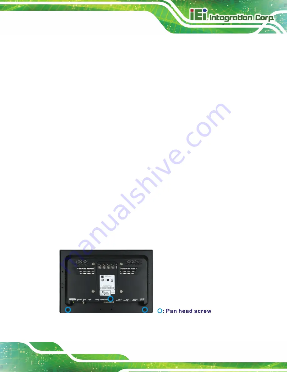
Remove the retention screws from the back cover. Two types of screw are used
for securing the back cover of the 12.1" and 15.6" models. See the following
diagrams for detail. Be aware of this for reinstalling the back cover.
Figure 3-1: AFL3-W10A-AL Back Cover Retention Screws
Summary of Contents for AFL3-W10A-AL
Page 15: ...AFL3 W10A 12A W15A AL Panel PC Page 1 1 Introduction Chapter 1...
Page 27: ...AFL3 W10A 12A W15A AL Panel PC Page 13 2 Unpacking Chapter 2...
Page 33: ...AFL3 W10A 12A W15A AL Panel PC Page 19 3 Installation Chapter 3...
Page 71: ...AFL3 W10A 12A W15A AL Panel PC Page 57 4 BIOS Setup Chapter 4...
Page 104: ...AFL3 W10A 12A W15A AL Panel PC Page 90 5 System Maintenance Chapter 5...
Page 108: ...AFL3 W10A 12A W15A AL Panel PC Page 94 6 Interface Connectors Chapter 6...
Page 125: ...AFL3 W10A 12A W15A AL Panel PC Page 111 Appendix A A Regulatory Compliance...
Page 131: ...AFL3 W10A 12A W15A AL Panel PC Page 117 B Safety Precautions Appendix B...
Page 137: ...AFL3 W10A 12A W15A AL Panel PC Page 123 C BIOS Menu Options Appendix C...
Page 140: ...AFL3 W10A 12A W15A AL Panel PC Page 126 Appendix D D Watchdog Timer...
Page 143: ...AFL3 W10A 12A W15A AL Panel PC Page 129 Appendix E E Hazardous Materials Disclosure...


