


AFL3-W07A-BT Panel PC
Page 23
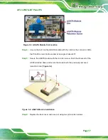
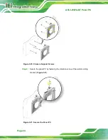
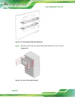
Step 6:
Insert the four monitor mounting screws provided in the wall mount kit into the
four screw holes on the real panel of the flat bezel panel PC and tighten until the
screw shank is secured against the rear panel (
WARNING:
Please use the M4 screws provided in the wall mount kit for the rear panel.
If the screw is missing, the thread depth of the replacement screw should
be not more than 4 mm.
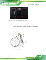
Step 7:
Align the mounting screws on the monitor rear panel with the mounting holes on
the bracket.
Step 8:
Carefully insert the screws through the holes and gently pull the monitor
downwards until the monitor rests securely in the slotted holes (
).
Ensure that all four of the mounting screws fit snugly into their respective slotted
holes.
NOTE:
In the diagram below the bracket is already installed on the wall.
Summary of Contents for AFL3-W07A-BT-N1/PC/2G-R20
Page 13: ...AFL3 W07A BT Panel PC Page 1 1 Introduction Chapter 1 ...
Page 21: ...AFL3 W07A BT Panel PC Page 9 2 Unpacking Chapter 2 ...
Page 25: ...AFL3 W07A BT Panel PC Page 13 3 Installation Chapter 3 ...
Page 54: ...AFL3 W07A BT Panel PC Page 42 4 BIOS Setup Chapter 4 ...
Page 82: ...AFL3 W07A BT Panel PC Page 70 5 System Maintenance Chapter 5 ...
Page 88: ...AFL3 W07A BT Panel PC Page 76 6 Interface Connectors Chapter 6 ...
Page 99: ...AFL3 W07A BT Panel PC Page 87 Appendix A A Regulatory Compliance ...
Page 104: ...AFL3 W07A BT Panel PC Page 92 B Safety Precautions Appendix B ...
Page 109: ...AFL3 W07A BT Panel PC Page 97 C BIOS Menu Options Appendix C ...
Page 112: ...AFL3 W07A BT Panel PC Page 100 Appendix D D Watchdog Timer ...
Page 115: ...AFL3 W07A BT Panel PC Page 103 E Hazardous Materials Disclosure Appendix E ...