


AFL3-W07A-BT Panel PC
Page 15
Anti-static Discharge
: If a user open the rear panel of the flat bezel panel PC,
to configure the jumpers or plug in added peripheral devices, ground
themselves first and wear an anti-static wristband.
3.3 Installation and Configuration Steps
The following installation steps must be followed.
Step 1:
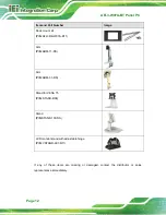
Unpack the flat bezel panel PC.
Step 2:
Install an mSATA module.
Step 3:
Configure the system.
Step 4:
Connect peripheral devices to the flat bezel panel PC.
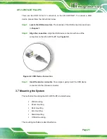
Step 5:
Mount the flat bezel panel PC.
Step 0:
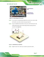
3.4 mSATA Module Installation
WARNING:
Over-tightening back cover screws will crack the plastic frame.
Maximum torque for cover screws is 5 kg-cm (0.36 lb-ft/0.49 Nm).
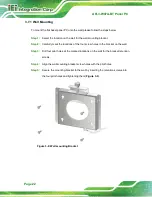
To install an mSATA module into the AFL3-W07A-BT, please follow the steps below:
Step 1:
Remove two (2) retention screws from the back cover (
Summary of Contents for AFL3-W07A-BT-N1/PC/2G-R20
Page 13: ...AFL3 W07A BT Panel PC Page 1 1 Introduction Chapter 1 ...
Page 21: ...AFL3 W07A BT Panel PC Page 9 2 Unpacking Chapter 2 ...
Page 25: ...AFL3 W07A BT Panel PC Page 13 3 Installation Chapter 3 ...
Page 54: ...AFL3 W07A BT Panel PC Page 42 4 BIOS Setup Chapter 4 ...
Page 82: ...AFL3 W07A BT Panel PC Page 70 5 System Maintenance Chapter 5 ...
Page 88: ...AFL3 W07A BT Panel PC Page 76 6 Interface Connectors Chapter 6 ...
Page 99: ...AFL3 W07A BT Panel PC Page 87 Appendix A A Regulatory Compliance ...
Page 104: ...AFL3 W07A BT Panel PC Page 92 B Safety Precautions Appendix B ...
Page 109: ...AFL3 W07A BT Panel PC Page 97 C BIOS Menu Options Appendix C ...
Page 112: ...AFL3 W07A BT Panel PC Page 100 Appendix D D Watchdog Timer ...
Page 115: ...AFL3 W07A BT Panel PC Page 103 E Hazardous Materials Disclosure Appendix E ...