background image


AFL3-W07A-AL Panel PC 


Page 102 

此附件旨在确保本产品符合中国

RoHS

标准。以下表格标示此产品中某有毒物质的含量符

合中国

RoHS

标准规定的限量要求。


本产品上会附有

环境友好使用期限

的标签,此期限是估算这些物质

不会有泄漏或突变

年限。本产品可能包含有较短的环境友好使用期限的可替换元件,像是电池或灯管,这些元

件将会单独标示出来。


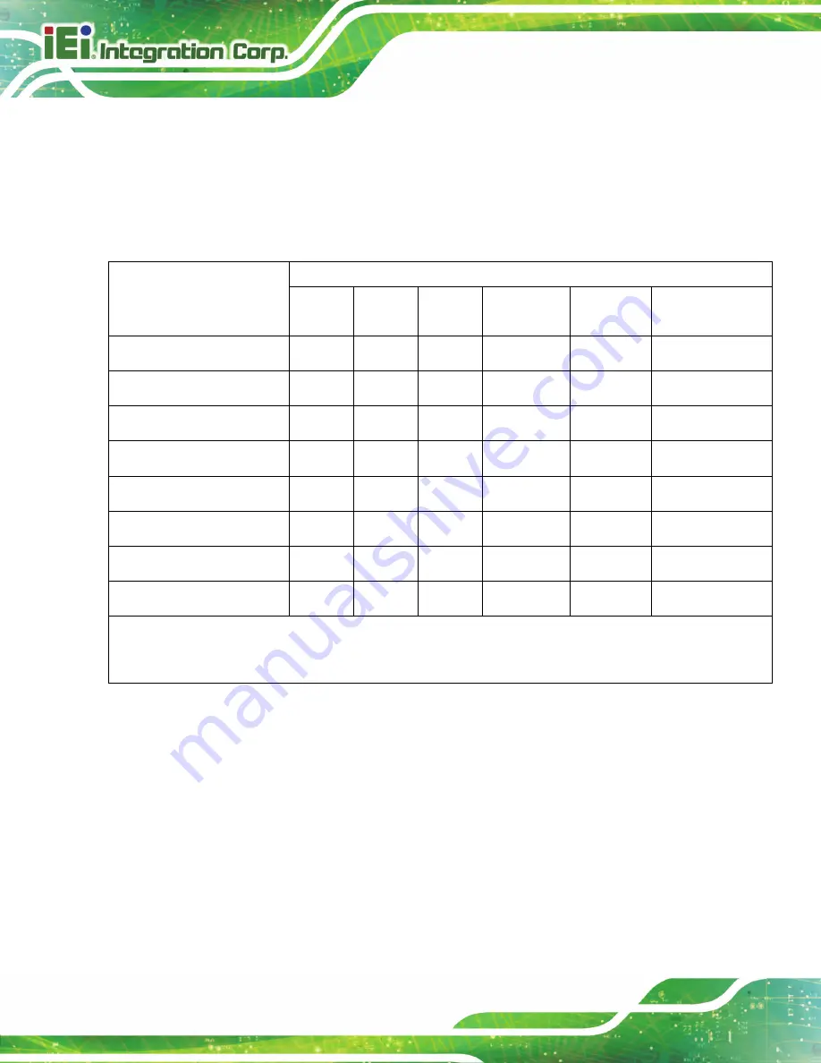
部件名称


有毒有害物质或元素


(Pb) 


(Hg) 


(Cd) 

六价铬


(CR(VI)) 

多溴联苯


(PBB) 

多溴二苯醚


(PBDE) 

壳体


显示


印刷电路板


金属螺帽


电缆组装


风扇组装


电力供应组装


电池


O: 

表示该有毒有害物质在该部件所有物质材料中的含量均在

SJ/T11363-2006 

标准规定的限量要求以下。


X: 

表示该有毒有害物质至少在该部件的某一均质材料中的含量超出

SJ/T11363-2006 

标准规定的限量要求。


Summary of Contents for AFL3-W07A-AL

Page 1: ...ge I User Manual AFL3 W07A AL MODEL 7 Flat Bezel Panel PC with Intel Celeron N3350 CPU Touchscreen Dual USB 3 1 Gen 1 M 2 B Key Slot Dual GbE LAN PoE PD Wi Fi 802 11a b g n ac and RoHS Rev 1 00 Septem...

Page 2: ...AFL3 W07A AL Panel PC Page II Revision Date Version Changes September 11 2019 1 00 Initial release...

Page 3: ...arising out of the use or inability to use the product or documentation even if advised of the possibility of such damages This document contains proprietary information protected by copyright All ri...

Page 4: ...N Cautionary messages should be heeded to help reduce the chance of losing data or damaging the product NOTE These messages inform the reader of essential but non critical information These messages s...

Page 5: ...INSTALLATION 13 3 1 ANTI STATIC PRECAUTIONS 14 3 2 INSTALLATION PRECAUTIONS 14 3 3 INSTALLATION AND CONFIGURATION STEPS 15 3 4 M 2 SSD INSTALLATION 15 3 5 AT ATX MODE SELECTION 18 3 5 1 AT Power Mode...

Page 6: ...2 iWDD H W Monitor 45 4 3 3 USB Configuration 46 4 3 4 CPU Configuration 47 4 3 5 RTC Wake Settings 49 4 3 6 Power Saving Configuration 50 4 3 7 iEi Feature 51 4 4 CHIPSET 52 4 4 1 North Bridge Config...

Page 7: ..._1 78 6 2 7 Power LED Connector PW_LED1 79 6 2 8 Speaker Connector Left SPK_L1 79 6 2 9 SPI Flash Connector J_SPI1 79 6 2 10 SPI Flash Connector EC J_SPI2 80 6 2 11 USB 2 0 Connector TOUCH_USB1 80 6 2...

Page 8: ...III B 2 2 Cleaning Tools 92 C BIOS MENU OPTIONS 93 D WATCHDOG TIMER 96 E HAZARDOUS MATERIALS DISCLOSURE 99 E 1 HAZARDOUS MATERIAL DISCLOSURE TABLE FOR IPB PRODUCTS CERTIFIED AS ROHS COMPLIANT UNDER 20...

Page 9: ...e 3 10 Panel Mounting Kit Installation 23 Figure 3 11 Securing Panel Mounting Brackets 24 Figure 3 12 Rack Cabinet Bracket Installation 25 Figure 3 13 Rack Mounting Kit Installation 26 Figure 3 14 Sec...

Page 10: ...AFL3 W07A AL Panel PC Page X Figure 5 2 WLAN Card Location 71 Figure 6 1 Main Board Layout Diagram Front Side 73 Figure 6 2 Main Board Layout Diagram Solder Side 73...

Page 11: ...B Key Slot M2_1 Pinouts 79 Table 6 8 Power LED Connector PW_LED1 Pinouts 79 Table 6 9 Left Speaker Connector SPK_L1 Pinouts 79 Table 6 10 SPI Flash Connector J_SPI1 Pinouts 79 Table 6 11 EC SPI Flash...

Page 12: ...Menu 8 Power Saving Configuration 50 BIOS Menu 9 iEi Feature 51 BIOS Menu 10 Chipset 52 BIOS Menu 11 North Bridge Configuration 53 BIOS Menu 12 Internal IGD Configuration 53 BIOS Menu 13 LCD Control...

Page 13: ...AFL3 W07A AL Panel PC Page 1 1 Introduction Chapter 1...

Page 14: ...ed bottlenecks and fast system access Two external USB 3 1 Gen 1 ports and two external USB 2 0 ports ensure simplified connectivity to a variety of external peripheral devices Wi Fi capabilities and...

Page 15: ...a power LED indicator located on the front panel The status descriptions of the power LED indicator are listed below Off power cord not attached or power supply failure Solid amber the system is conne...

Page 16: ...V DC input power jack 1 x GbE LAN PoE RJ 45 connector 1 x GbE LAN RJ 45 connector 2 x USB 3 1 Gen 1 connector 2 x USB 2 0 connector 1 x AT ATX switch 1 x Power button 1 x Reset button 1 x Clear CMOS...

Page 17: ...technical specifications for the AFL3 W07A AL systems are listed in Table 1 4 Specification AFL3 W07A AL LCD Size 7 16 9 Max Resolution 1024 W x 600 H Brightness cd m2 500 Contrast Ratio 700 1 LCD Col...

Page 18: ...channel output only Wireless One 802 11a b g n ac wireless LAN module via M 2 A key 2230 slot with PCIe USB signal supports Bluetooth v4 1 Construction Material PC ABS plastic front frame Mounting VES...

Page 19: ...s connectors 2 x USB 2 0 connectors 1 x 12 V DC input jack 1 x Power button 1 x Reset button 1 x Clear CMOS button 1 x AT ATX switch Table 1 1 System Specifications NOTE When both DC in and PoE are co...

Page 20: ...AFL3 W07A AL Panel PC Page 8 1 7 Dimensions The AFL3 W07A AL dimensions are shown below Width 190 9 mm Height 127 3 mm Depth 43 4 mm Figure 1 5 AFL3 W07A AL Dimensions mm...

Page 21: ...AFL3 W07A AL Panel PC Page 9 2 Unpacking Chapter 2...

Page 22: ...the installation process Step 1 Use box cutters a knife or a sharp pair of scissors that seals the top side of the external second box Step 2 Open the external second box Step 3 Use box cutters a kni...

Page 23: ...owing components Quantity Item Image 1 AFL3 W07A AL panel PC 1 Power adapter 36 W 1 Power cord 4 Screws for VESA mounting 1 Thermal pad for M 2 SSD module 2 3 Optional Items The following are optional...

Page 24: ...11 Rack mount kit P N AFL3RK W07A R11 Arm P N ARM 11 RS Arm P N ARM 31 RS Stand for VESA 75 P N STAND B08 Stand P N STAND 100 RS LCD monitor stand with adjustable hinge P N VSTAND A07 R11 If any of th...

Page 25: ...AFL3 W07A AL Panel PC Page 13 3 Installation Chapter 3...

Page 26: ...revent ESD from damaging the board Self grounding Before handling the board touch any grounded conducting material During the time the board is handled frequently touch any conducting materials that a...

Page 27: ...followed Step 1 Unpack the flat bezel panel PC Step 2 Install an mSATA module Step 3 Configure the system Step 4 Connect peripheral devices to the flat bezel panel PC Step 5 Mount the flat bezel panel...

Page 28: ...ver Retention Screws Step 2 Remove the back cover from the device See Figure 3 2 Figure 3 2 Open the Back Cover Step 3 Locate the M 2 B key 2242 slot Remove the preinstalled retention screw on the scr...

Page 29: ...e 3 4 Step 5 Secure the M 2 SSD with the retention screw Push the other end of the M 2 SSD down and secure the card with the previously removed retention screw Figure 3 4 Figure 3 4 M 2 SSD Installati...

Page 30: ...ne to control multiple panel PCs from a central management center and other applications including ATM Self service kiosk Plant environment monitoring system Factory automation platform Manufacturing...

Page 31: ...e wall please follow the steps below Step 1 Select the location on the wall for the wall mounting bracket Step 2 Carefully mark the locations of the four screw holes in the bracket on the wall Step 3...

Page 32: ...nt kit into the four screw holes on the real panel of the flat bezel panel PC and tighten until the screw shank is secured against the rear panel Figure 3 7 WARNING Please use the M4 screws provided i...

Page 33: ...y pull the monitor downwards until the monitor rests securely in the slotted holes Figure 3 7 Ensure that all four of the mounting screws fit snugly into their respective slotted holes NOTE In the dia...

Page 34: ...the AFL3 W07A AL flat bezel panel PC into a panel please follow the steps below Step 1 Select the position on the panel to mount the flat bezel panel PC Step 2 Cut out a section corresponding to the...

Page 35: ...the following components onto the screw in sequence See Figure 3 10 Sequence Item Photo Instruction 1 Spring Install a spring onto the screw 2 Nut Tighten a nut until the spring is compressed enough...

Page 36: ...re the two panel mounting brackets to the rear of the panel PC by inserting the four retention screws into the VESA mounting holes and tightening them Figure 3 11 S t e p 0 NOTE The panel mounting kit...

Page 37: ...AFL3 W07A AL flat bezel panel PC and the rack cabinet into which the AFL3 W07A AL is installed Step 1 Slide the rear chassis of the AFL3 W07A AL flat bezel panel PC through the rack cabinet bracket u...

Page 38: ...ll the other three screws into the sides of the two rack mounting brackets Figure 3 13 Rack Mounting Kit Installation Step 4 Align the rack mounting bracket screw holes with the VESA mounting holes on...

Page 39: ...kit described in this section is an optional item To purchase it please contact an IEI sales representative Figure 3 14 Securing Rack Mounting Brackets Step 6 Slide the panel PC with the attached rac...

Page 40: ...f the rack or cabinet Figure 3 15 3 6 4 Arm Mounting The AFL3 W07A AL is VESA Video Electronics Standards Association compliant and can be mounted on an arm with a 75 mm interface pad To mount the AFL...

Page 41: ...ce the mounting arm has been firmly attached to the surface lift the flat bezel panel PC onto the interface pad of the mounting arm Step 3 Align the retention screw holes on the mounting arm interface...

Page 42: ...tand mounting kit please follow the steps below Step 1 Locate the screw holes on the rear of the AFL3 W07A AL This is where the bracket will be attached Step 2 Align the bracket with the screw holes S...

Page 43: ...V Stand Mounting To mount the AFL3 W07A AL using the V Stand mounting kit please follow the steps below Step 1 Carefully mark the locations of the four V Stand screw holes on the mounting area Drill...

Page 44: ...e V Stand with the VESA mount screw holes on the system rear panel Step 3 Insert the four VESA mount screws into the four screw holes on the system rear panel Adjust the V Stand to a proper position S...

Page 45: ...e the system S t e p 0 Figure 3 21 Secure V Stand to Mounting Area 3 7 Powering On the System To power on the system follow the steps below Step 1 Connect the power cord to the power adapter Connect t...

Page 46: ...DC in and PoE are connected to the device the DC in will be used as the main power source Disconnecting DC in while the system is running may lead to system shutdown or reboot To switch to the PoE mo...

Page 47: ...button to reboot the system Figure 3 23 Reset Button Location 3 9 Clear CMOS If the AFL3 W07A AL fails to boot due to improper BIOS settings the clear CMOS button clears the CMOS data and resets the s...

Page 48: ...ess Enter to find all the relevant software utilities and documentation Figure 3 25 IEI Resource Download Center NOTE To install software from the downloaded ISO image file in Windows 8 8 1 or 10 doub...

Page 49: ...AFL3 W07A AL and press Enter Step 2 All product related software utilities and documentation will be listed You can choose Driver to filter the result Step 3 Click the driver file name on the page an...

Page 50: ...AFL3 W07A AL Panel PC Page 38...

Page 51: ...AFL3 W07A AL Panel PC Page 39 4 BIOS Setup Chapter 4...

Page 52: ...The UEFI BIOS is activated when the computer is turned on The setup program can be activated in one of two ways 1 Press the DEL key as soon as the system is turned on or 2 Press the DEL key when the...

Page 53: ...Table 6 1 BIOS Navigation Keys 4 1 3 Getting Help When F1 is pressed a small help window describing the appropriate keys to use and the possible selections for the highlighted item appears To exit th...

Page 54: ...endor American Megatrends Core Version 5 12 Compliency UEFI 2 5 PI 1 4 Project Version Z571AR10 ROM Build Date and Time 04 23 2019 11 39 09 iWDD Vendor iEi iWDD Version Z571ER11 bin Platform firmware...

Page 55: ...wrong values in the sections below may cause the system to malfunction Make sure that the settings made are compatible with the hardware Aptio Setup Utility Copyright C 2019 American Megatrends Inc Ma...

Page 56: ...D button is pressed Select Screen Select Item EnterSelect Change Opt F1 General Help F2 Previous Values F3 Optimized Defaults F4 Save Exit ESC Exit Version 2 18 1263 Copyright C 2019 American Megatren...

Page 57: ...11 774 V DDR 1 343 V 5VSB 5 038 V 3 3V 3 296 V 3 3VSB 3 317 V Select Screen Select Item EnterSelect Change Opt F1 General Help F2 Previous Values F3 Optimized Defaults F4 Save Exit ESC Exit Version 2...

Page 58: ...ral Help F2 Previous Values F3 Optimized Defaults F4 Save Exit ESC Exit Version 2 18 1263 Copyright C 2019 American Megatrends Inc BIOS Menu 5 USB Configuration USB Devices The USB Devices Enabled fie...

Page 59: ...tel HT Technology Not Supported Intel VT x Technology Supported L1 Data Cache 24 KB x 2 L1 Code Cache 32 KB x 2 L2 Cache 1024 KB x 2 L3 Cache Not Present EIST Enabled C States Disabled Intel Virtualiz...

Page 60: ...hnology option to enable or disable virtualization on the system When combined with third party software Intel Virtualization technology allows several OSs to run on the same system at the same time D...

Page 61: ...lues F3 Optimized Defaults F4 Save ESC Exit Version 2 18 1263 Copyright C 2019 American Megatrends Inc BIOS Menu 7 RTC Wake Settings Wake System with Fixed Time Disabled Use the Wake System with Fixed...

Page 62: ...to reduce power consumption in system off state Select Screen Select Item EnterSelect F1 General Help F2 Previous Values F3 Optimized Defaults F4 Save ESC Exit Version 2 18 1263 Copyright C 2019 Ameri...

Page 63: ...shes Please install Auto Recovery API service before enabling this function Select Screen Select Item Enter Select Change Opt F1 General Help F2 Previous Values F3 Optimized Defaults F4 Save Exit ESC...

Page 64: ...in the Chipset BIOS menu may cause the system to malfunction Aptio Setup Utility Copyright C 2019 American Megatrends Inc Main Advanced Chipset Security Boot Save Exit North Bridge South Bridge North...

Page 65: ...opyright C 2019 American Megatrends Inc BIOS Menu 11 North Bridge Configuration 4 4 1 1 Internal IGD Configuration Use the Internal IGD Configuration BIOS Menu 12 menu to set the integrated graphics A...

Page 66: ...stem memory allocated to the integrated graphics processor when the system boots The system memory allocated can then only be used as graphics memory and is no longer available to applications or the...

Page 67: ...vice which will be activated during POST This has no effect if external graphics present Secondary boot display selection will appear based on your selection VGA modes will be supported only on primar...

Page 68: ...South Bridge Configuration menu BIOS Menu 11 to configure the south bridge chipset Aptio Setup Utility Copyright C 2019 American Megatrends Inc Chipset Auto Power Button Function Disable ATX HD Audio...

Page 69: ...t turns itself on If it was off it remains off USB Power SW1 5V DUAL Use the USB Power SW1 BIOS option to configure whether to provide power to the external USB 3 1 Gen 1 connectors when the system is...

Page 70: ...Select Screen Select Item EnterSelect F1 General Help F2 Previous Values F3 Optimized Defaults F4 Save ESC Exit Version 2 18 1263 Copyright C 2019 American Megatrends Inc BIOS Menu 15 HD Audio Configu...

Page 71: ...Aptio Setup Utility Copyright C 2019 American Megatrends Inc Chipset PCI Express Configuration M2_AKEY1 Compliance Mode Enable Disable Select Screen Select Item EnterSelect F1 General Help F2 Previous...

Page 72: ...speed Select Screen Select Item Enter Select Change Opt F1 General Help F2 Previous Values F3 Optimized Defaults F4 Save Exit ESC Exit Version 2 18 1263 Copyright C 2019 American Megatrends Inc BIOS M...

Page 73: ...roller supports the 2 black internal SATA ports up to 3Gb s supported per port Select Screen Select Item EnterSelect F1 General Help F2 Previous Values F3 Optimized Defaults F4 Save ESC Exit Version 2...

Page 74: ...word and must be entered to boot or enter Setup In Setup the User will have Administrator rights The password must be In the following range Maximum length 3 Minimum length 20 Administrator Password U...

Page 75: ...on 2 18 1263 Copyright C 2019 American Megatrends Inc BIOS Menu 20 Boot Bootup NumLock State On Use the Bootup NumLock State BIOS option to specify if the number lock setting must be modified during b...

Page 76: ...le or disable boot option for legacy network devices Disabled DEFAULT Ignore all PXE Option ROMs Enabled Load PXE Option ROMs Option ROM Messages Force BIOS Use the Option ROM Messages option to set t...

Page 77: ...t Item EnterSelect Change Opt F1 General Help F2 Previous Values F3 Optimized Defaults F4 Save Exit ESC Exit Version 2 18 1263 Copyright C 2019 American Megatrends Inc BIOS Menu 21 Save Exit Save Chan...

Page 78: ...e 66 Save as User Defaults Use the Save as User Defaults option to save the changes done so far as user defaults Restore User Defaults Use the Restore User Defaults option to restore the user defaults...

Page 79: ...AFL3 W07A AL Panel PC Page 67 5 System Maintenance Chapter 5...

Page 80: ...AL Dry climates are especially susceptible to ESD It is therefore critical that whenever the AFL3 W07A AL is accessed internally or any other electrical component is handled the following anti static...

Page 81: ...out on the system make sure the system is turned off 5 4 Removing the Back Cover WARNING Over tightening back cover screws will crack the plastic frame Maximum torque for cover screws is 5 kg cm 0 36...

Page 82: ...cover from the chassis and lift the cover of the device Step 0 5 5 WLAN Card Replacement The AFL3 W07A AL has one WLAN card slot To replace the WLAN card follow the instructions below Step 1 Follow a...

Page 83: ...into the slot at an angle Step 8 Push the WLAN card down and secure it with the previously removed retention screw Step 9 Connect the antenna cables Step 10 Replace the back cover and secure it using...

Page 84: ...AFL3 W07A AL Panel PC Page 72 6 Interface Connectors Chapter 6...

Page 85: ...connectors and configuration jumpers The connector locations are shown in Figure 6 1 The Pin 1 locations of the on board connectors are also indicated in the diagram below The connector pinouts for th...

Page 86: ...Battery connector 2 pin wafer BT1 Debug port 12 pin wafer 80PORT1 HDMI connector HDMI port HDMI1 LVDS connector 40 pin FPC LVDS2 M 2 A key slot M 2 A key M2_AKEY1 M 2 B key slot M 2 B key M2_1 Power...

Page 87: ...AD2 12 GND Table 6 3 Debug Port Connector 80PORT1 Pinouts 6 2 3 Internal HDMI Connector HDMI1 PIN NO DESCRIPTION PIN NO DESCRIPTION 1 HDMI_DATA2 2 GND 3 HDMI_DATA2 4 HDMI_DATA1 5 GND 6 HDMI_DATA1 7 HD...

Page 88: ...DSA0 29 VCC_LCD_AVDD 10 GND 30 GND 11 LVDSA1 31 VLED 12 LVDSA1 32 VLED 13 GND 33 LCD_LR 14 LVDSA2 34 LCD_UD 15 LVDSA2 35 LCD_VGL 16 GND 36 LCD_CABC_EN1 17 LVDSACLK 37 LCD_CABC_EN0 18 LVDSACLK 38 LCD_V...

Page 89: ...34 NC 35 PCIE_TX 36 GND 37 PCIE_TX 38 NC 39 GND 40 NC 41 PCIE_RX 42 NC 43 PCIE_RX 44 NC 45 GND 46 NC 47 CLK_PCIE 48 NC 49 CLK_PCIE 50 NC 51 GND 52 BUF_PLT_RST 53 PCIE_CLKREQ 54 Pull Up V3 3A 55 PCIE_W...

Page 90: ...3 GND 24 N C 25 N C 26 N C 27 N C 28 N C 29 USB3_RX2_N 30 N C 31 USB3_RX2_P 32 N C 33 GND 34 N C 35 USB3P0_TXDNM2 36 N C 37 USB3P0_TXDPM2 38 GND 39 GND 40 N C 41 M1_SATA_RX1 _C 42 N C 43 M1_SATA_RX1 _...

Page 91: ...DESCRIPTION 1 5VS 2 GND 3 5VA Table 6 8 Power LED Connector PW_LED1 Pinouts 6 2 8 Speaker Connector Left SPK_L1 PIN NO DESCRIPTION 1 SPK_OUT_L 2 SPK_OUT_L Table 6 9 Left Speaker Connector SPK_L1 Pino...

Page 92: ...I_SI_SW 6 GND Table 6 11 EC SPI Flash Connector J_SPI2 Pinouts 6 2 11 USB 2 0 Connector TOUCH_USB1 PIN NO DESCRIPTION 1 5V 2 USB_DATA 3 USB_DATA 4 GND Table 6 12 USB 2 0 Connector TOUCH_USB1 Pinouts 6...

Page 93: ...ton PWR_BTN1 Power connector Power jack PWR1 USB 2 0 connectors USB 2 0 Type A USB20_CN2 USB 3 0 connectors USB 3 1 Gen 1 Type A USB3 1 Table 6 14 Rear Panel Connectors 6 3 1 Ethernet Connectors LAN1...

Page 94: ...le 6 18 USB 2 0 Connectors USB20_CN2 Pinouts 6 3 4 USB 3 1 Gen 1 Connectors USB3 1 PIN NO DESCRIPTION PIN NO DESCRIPTION 1 USB3_PWR1 10 USB3_PWR2 2 USB2P0_DM1_L 11 USB2P0_DM2_L 3 USB2P0_DP1_L 12 USB2P...

Page 95: ...AFL3 W07A AL Panel PC Page 83 Appendix A A Regulatory Compliance...

Page 96: ...ial requirements and other relevant provisions of Directive 1999 5 EC Bulgarian IEI Integration Corp 1999 5 esky Czech IEI Integration Corp t mto prohla uje e tento za zen je ve shod se z kladn mi po...

Page 97: ...Lietuvi Lithuanian IEI Integration Corp deklaruoja kad is ranga atitinka esminius reikalavimus ir kitas 1999 5 EB Direktyvos nuostatas Nederlands Dutch IEI In egration Corp dat het toestel toestel in...

Page 98: ...ili direktive 1999 5 ES Slovensky Slovak IEI Integration Corp t mto vyhlasuje e zariadenia sp a z kladn po iadavky a v etky pr slu n ustanovenia Smernice 199 5 ES Suomi Finnish IEI Integration Corp v...

Page 99: ...ference at his own expense Federal Communication Commission Interference Statement This equipment has been assembled with components that comply with the limits for a Class B digital device pursuant t...

Page 100: ...AFL3 W07A AL Panel PC Page 88 B Safety Precautions Appendix B...

Page 101: ...henever the AFL3 W07A AL is being installed moved or modified Do not apply voltage levels that exceed the specified voltage range Doing so may cause fire and or an electrical shock Electric shocks can...

Page 102: ...ollowing anti static precautions are strictly adhered to Wear an anti static wristband Wearing a simple anti static wristband can help to prevent ESD from damaging any electrical component Self ground...

Page 103: ...l and electronic products carrying the mark left must be disposed of separately from normal household waste This includes monitors and electrical accessories such as signal cables or power cords When...

Page 104: ...ols Some components in the AFL3 W07A AL may only be cleaned using a product specifically designed for the purpose In such case the product will be explicitly mentioned in the cleaning tips Below is a...

Page 105: ...AFL3 W07A AL Panel PC Page 93 C BIOS Menu Options Appendix C...

Page 106: ...ed 51 Primary Display IGD 54 DVMT Pre Allocated 256MB 54 DVMT Total Gfx Mem MAX 54 Primary IGFX Boot Display Auto 55 Backlight Control Mode LED 56 Backlight Control Type PWM 56 Restore on AC Power Los...

Page 107: ...AFL3 W07A AL Panel PC Page 95 Save as User Defaults 66 Restore User Defaults 66...

Page 108: ...AFL3 W07A AL Panel PC Page 96 Appendix D D Watchdog Timer...

Page 109: ...H AH 6FH Sub function AL 2 Sets the Watchdog Timer s period BL Time out value Its unit second is dependent on the item Watchdog Timer unit select in CMOS setup Table D 1 AH 6FH Sub function Call sub f...

Page 110: ...not deactivated the system will automatically restart after the Timer has finished its countdown EXAMPLE PROGRAM INITIAL TIMER PERIOD COUNTER W_LOOP MOV AX 6F02H setting the time out value MOV BL 30...

Page 111: ...AFL3 W07A AL Panel PC Page 99 E Hazardous Materials Disclosure Appendix E...

Page 112: ...presences of small quantities of certain materials in the product and is applicable to China RoHS only A label will be placed on each product to indicate the estimated Environmentally Friendly Use Per...

Page 113: ...t Board O O O O O O Metal Fasteners O O O O O O Cable Assembly O O O O O O Fan Assembly O O O O O O Power Supply Assemblies O O O O O O Battery O O O O O O O This toxic or hazardous substance is conta...

Page 114: ...AFL3 W07A AL Panel PC Page 102 RoHS RoHS Pb Hg Cd CR VI PBB PBDE O O O O O O O O O O O O O O O O O O O O O O O O O O O O O O O O O O O O O O O O O O O O O O O O O SJ T11363 2006 X SJ T11363 2006...

Reviews: