


AFL-W19A/W19B/17D/W15A-GM45 Panel PC
Page 23
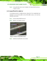
Figure 2-8: LAN Connection
Step 3:
Insert the LAN cable RJ-45 connector.
Once aligned, gently insert the LAN
cable RJ-45 connector into the onboard RJ-45 port.
Step 0:
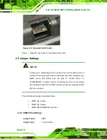
2.7.2 Serial Device Connection
The serial device connectors are for connecting serial devices to the
AFL-W19A/W19B/17D/W15A-GM45. Follow the steps below to connect a serial device to
the AFL-W19A/W19B/17D/W15A-GM45 panel PC.
Step 1:
Locate the DB-9 connector
. The location of the DB-9 connector is shown in
5
Insert the serial connector
.
Insert the DB-9 connector of a serial device into
the DB-9 connector on the bottom panel. See
5
Figure 2-9.
Summary of Contents for AFL-17D
Page 12: ...AFL W19A W19B 17D W15A GM45 Panel PC Page 1 Chapter 1 1 Introduction...
Page 22: ...AFL W19A W19B 17D W15A GM45 Panel PC Page 11 Chapter 2 2 Installation...
Page 39: ...AFL W19A W19B 17D W15A GM45 Panel PC Page 28 Chapter 3 3 BIOS...
Page 86: ...AFL W19A W19B 17D W15A GM45 Panel PC Page 75 Chapter 4 4 System Maintenance...
Page 89: ...AFL W19A W19B 17D W15A GM45 Panel PC Page 78 Figure 4 2 DDR SO DIMM Module Installation...
Page 90: ...AFL W19A W19B 17D W15A GM45 Panel PC Page 79 Appendix A A Safety Precautions...
Page 95: ...AFL W19A W19B 17D W15A GM45 Panel PC Page 84 Appendix B B BIOS Options...
Page 99: ...AFL W19A W19B 17D W15A GM45 Panel PC Page 88 Appendix C C One Key Recovery...
Page 107: ...AFL W19A W19B 17D W15A GM45 Panel PC Page 96 Figure C 5 Partition Creation Commands...
Page 141: ...AFL W19A W19B 17D W15A GM45 Panel PC Page 130 Appendix D D Terminology...
Page 145: ...AFL W19A W19B 17D W15A GM45 Panel PC Page 134 Appendix E E Watchdog Timer...
Page 148: ...AFL W19A W19B 17D W15A GM45 Panel PC Page 137 Appendix F F Hazardous Materials Disclosure...